UAZ loaf steering column with guru analysis. How to remove the steering column of a UAZ Bukhanka
Perform this to eliminate gaps that appear during the running-in of the working worm-roller pair and its wear during vehicle operation. The working pair of the steering mechanism is designed in such a way that when the roller position corresponds to the vehicle moving in a straight line, the engagement gap is practically equal to zero. As the wheel turns in one direction or another, the engagement gap gradually increases, reaching its greatest value in the extreme positions of the roller. The condition of the steering mechanism is considered normal and does not require adjustment if the free play of the steering wheel in the straight-line position does not exceed 10°, which corresponds to 40 mm when measured at the wheel rim. If the steering wheel play is more than specified, then before proceeding to adjust the steering mechanism, make sure that the crankcase mounting bolts are tightly tightened and that the drive joints are in good condition.
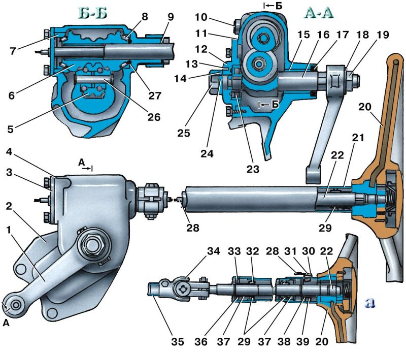
Units and parts of the UAZ-469 steering mechanism, spare parts: 1 - steering gear housing; 2 - bushing; 3 - oil seal; 4 - bipod: 5 - washer; 6 - nut; 7 - oil seal; 8 and 14 - worm bearings; 9 - plug; 10 - UAZ-469 steering shaft; 11 - worm; 12 - lower crankcase cover; 13 - gaskets; 15 - roller axis; 16 - bipod shaft roller; 17 - bipod shaft with roller and bearing; 18 - crankcase mounting bolts; 19 - hinge; 20 - retaining ring; 21 - protective washer; 22 - spring; 23 - spacer sleeve; 24 - bearings; 25 - horn wire; 26 - contact sleeve; 27 - screw; 28 and 29 - plastic bushings; 30 - steering wheel; 31 - steering shaft; 32 - adjusting screw; 33 - cap nut; 34 - lock washer; 35 - pin; 36 - weaving shaft bearing; 37 - side crankcase cover; 38 - gasket; 39 - bushing.
Adjust the tightening of the UAZ-469 worm bearings using gaskets 13 installed between the crankcase and the lower cover of the steering gear housing, in the following sequence:
1. Remove the steering gear from the vehicle.
2. Drain the oil from the crankcase.
3. Clamp the steering gear in a vice.
4. Unscrew cap nut 33 and remove lock washer 34 from adjusting screw 32.
5. Unscrew the bolts securing the side cover 37 of the crankcase.
6. Remove the bipod shaft 17 together with the cover by lightly hitting the end of the shaft with a copper or aluminum drift and carefully remove the gasket 38.
7. Unscrew the bolts securing the lower crankcase cover and remove the lower cover 12.
8. Carefully separate and remove the thin paper gasket 13.
9. Reinstall the bottom cover, tighten the bolts and check the axial movement of the worm.
10. If the axial movement remains, then remove the bottom cover again, remove the thick gasket, and install the previously removed thin gasket in its place. Do not remove more than one gasket.
If radial play appears in the hinge (axial movement of the cross in the bearings), perform additional core drilling of the bearings in the fork ears. Perform the core in such a way as to prevent the bearing cup from being crushed. The crosspiece bearings are lubricated with Litol-24 grease when assembled at the factory and there is no need to add it during operation. Next: Possible malfunctions of the UAZ-469 steering.
- Technical specifications UAZ-469, UAZ-469B
- Engine UAZ-469, UAZ-469B
- Transmission UAZ-469, UAZ-469B
- Controls of UAZ-469
- Preparing for work UAZ-469
- Engine mount UAZ-469
- Crank mechanism of the UAZ-469 engine
- Gas distribution mechanism of the UAZ-469 engine
- Lubrication system UAZ-469
- Engine crankcase ventilation system UAZ-469
- UAZ-469 engine power supply system
- Carburetor K-129V
- Gas exhaust system of the UAZ-469 engine
- UAZ-469 engine cooling system
- Preheater UAZ-469 engine
- UAZ-469 engine malfunctions
- Clutch UAZ-469
- Gearbox UAZ-469
- Transfer case UAZ-469
- Cardan transmission UAZ-469
- Rear axle UAZ-469
- Rear axle UAZ-469B
- Front drive axle UAZ-469
- UAZ-469 frame
- Suspension UAZ-469
- Steering of UAZ-469
- Brakes UAZ-469
- Electrics UAZ-469
- Generator UAZ-469
- Voltage regulator PP132
- Battery UAZ-469
- Ignition system UAZ-469
- Starter UAZ-469
- Lighting, light and sound alarm system UAZ-469
- Control and measuring instruments UAZ-469
- Tools and accessories UAZ-469
- Body of UAZ-469
- Marking UAZ-469
- Maintenance of UAZ-469
- Lubricants UAZ-469 and UAZ-469B
The cabin heater was made using a radiator from a KamAZ heater and two fans with electric motors from a UAZ 3151. On the front panel of the heater, I installed switches for the headlight cleaner, cabin heater, interior heater, door locks, cigarette lighter and ashtray. At the bottom of the panel on the right and left there are deflectors from VAZ 2105 to supply air to the feet of the driver and front passenger, in the middle part there are four VAZ 2107 deflectors to supply air to the cabin.
The interior heater was equipped with a more powerful electric motor with a larger diameter impeller. Air intake is only from the passenger compartment, and hot air is supplied through a pipe through adjustable nozzles from the VAZ 2105 to the feet of passengers in the cabin. The fluid supply to the heaters is completely separate and controlled from the cabin.
I removed the partition behind the cab and strengthened the body frame in the middle part. The battery (it is behind the driver's seat) was covered with a casing. It turned out to be a convenient place for a first aid kit and a warning triangle.
All four wheels have been fitted with mudguards, not installed by the factory, but required by traffic police inspectors. The standard sunroof was replaced with another one from KamAZ: it opens in all directions, which improves ventilation.
I installed upholstery on the front doors and personally assembled electric windows; there will also be locks with central locking. External mirrors - on racks from Gazelle - are mounted on brackets from KamAZ. If desired, they can be folded, reducing the size of the car. An additional mirror above the windshield serves as an overview of the interior.
I replaced all the seats with more comfortable ones from the decommissioned tourist Ikarus. The driver's seat has two adjustments: longitudinal and backrest angle. In the cabin I installed a folding table, which in the lower position “participates” in the formation of a berth, as well as six seats, three of which have adjustable backrest angles. The two middle seats in the back row are removable, allowing you to transport large items. I equipped tool boxes under the three seats of the cabin.
After all these replacements and modifications, both I and the passengers really like the car.
The homemade instrument panel features a modern Gazelle dashboard and key switches.
In a warm winter cabin with comfortable seats, passengers feel like they are in a nice bus.
Yuri KROMM, Novosibirsk zr.ru
Tuning or the preparation (construction) of an SUV is a protracted process that can almost never be completed, so it is better to carry it out in stages. And keep in mind that any SUV is very sensitive to any additional weight. Excess weight negatively affects the vehicle's maneuverability, and it also increases the load on the suspension, so try to avoid unnecessary parts. More details about tuning...
Forward! It’s worth starting, perhaps, with the simplest and most important improvements.
Stage 1. Replacing wheels.

The first stage of tuning is one of the most expensive, but it makes the car capable of competing with “big” off-road. Most cars leave the factory with 225/75 R16 or 235/70 R16 tires. Practice shows that when preparing a UAZ, tires with an outer diameter of 31, 33, 35 inches are optimal to increase cross-country ability. It is better to replace the wheels with 15-inch ones (they are cheaper and more often found in stores than 16-inch ones). The model and, accordingly, the wheel tread pattern depend on the application. The most versatile tires are the all terrain category - “general purpose”, i.e. having more or less equal characteristics at the most various types surfaces, from winter highways to liquid mud and deep sand, but this is not for serious off-roading. And the most popular are the BFGoodrich Mud-Terrain with an outer diameter of 35 inches. The cost of this stage will depend on the type and brand of the wheel and disk manufacturer, and ranges from 350 to 600 USD. for the wheel assembly. Read more about this tuning stage...
Stage 2. Body and suspension lift.

The second stage of tuning is inextricably linked with the first, since in order big wheels took their place, and when moving the suspension and turning the steering wheel they did not touch the arches, it is necessary to lift the car body above the frame - lift it, installing additional spacers between the frame and the body, and trim the wing arches. This will also increase maneuverability, especially in areas with large bumps, stumps, boulders, etc. In addition, the suspension lift will also increase cross-country ability: stones, logs, sharp ascents and descents will no longer be scary. The cost of this tuning stage depends on the degree of lifting and ranges from 200 to 500 USD. If the lift is especially serious character, then the cost increases in proportion to the work performed. Read more about this tuning stage...
Stage 3. Suspension.

The degree of suspension modification depends on the body lift and suspension. Preparing the UAZ requires adding additional sheets to the springs and installing shock absorbers with higher energy intensity. Sometimes we install two shock absorbers on each wheel. The cost of the third stage of tuning fluctuates around 300 USD. Read more about this tuning stage...
The first three stages lift the car significantly. However, what is good on difficult terrain is completely unacceptable on asphalt. Acceptable behavior on the highway can only be ensured by a suspension with high angular stiffness and the lowest possible position of the vehicle's center of gravity. Conclusion: to build a universal car, we are looking for a compromise.
Stage 4. Bridges.

UAZ vehicles are equipped with one of three types of axles. These are so-called: “civilian” bridges, “military” bridges, “spicer” type bridges. They all have non-locking cross-axle differentials. To increase cross-country ability, blocking devices (with forced locking or self-locking) are used. However, in our opinion, they should only be installed by those who know how to handle them, i.e. avoid jumping, sudden movement, violent slipping on mixed surfaces, etc., take into account speed mode and don’t forget to turn them off when they are no longer needed. average cost this stage is 700 USD. behind the bridge. Read more about this tuning stage...
Stage 5. Installation of disc brakes

This stage of tuning mainly applies to basic and older UAZ models (on new models, disc brakes come from the factory). It is necessary because sand and dirt getting into the drum brakes leads to uneven wear. And after crossing fords, swimming in mud baths, the brakes, even if the driver has dried them properly, behave, to put it mildly, inadequately - you can never predict which direction the car will pull the next time you brake. Disc brakes, unlike drum brakes, due to the fact that the pad is in contact with the disc along a plane and is always pressed tightly against the disc, have the ability to self-clean. It will cost 500 USD. Read more about this tuning stage...
Stage 6. Protection of units and body

A well-prepared jeep necessarily has a powerful bumper. The simplest and most reliable bumper is a thick pipe. Now they sell ready-made bumpers - RIF, which we recommend for installation, but you can weld an individual bumper, which will be cheaper and more powerful. Not only will it be stronger, but after “hard contact with the terrain” it can be easily tidied up with a sledgehammer...
Protective grille - " "
will protect the front of the car from “contact” with obstacles or when “diving” into mud or snow and ice slush.
Guy ropes(branches) will keep the windshield and A-pillars intact, taking on the blows of tree branches, from which the lighting devices also need to be protected. The thresholds will protect your car from impacts from the side, and will also serve as stops for a high-jack jack, allowing you to hang the wheel even in deep mud or snow.
Steering rod protection, engine compartment, axle housings, transfer cases, fuel tanks is simply necessary if you are moving through the forest, over rocky or unfamiliar terrain, overcoming fords or bumpy terrain.
We strongly recommend covering the floor, casings, and arches with aluminum panels. The explanation for this is simple. Dirt that sticks to shoes and gets into the interior of the SUV can be easily washed off from aluminum panels.
The cost of this stage directly depends on the work performed. Let’s indicate it only purely symbolically: from 200 USD. up to 2000 USD (and this is not a chapel). By choosing the optimal designs that meet the specified requirements, you can achieve the lowest cost of the SUV preparation project.
Stage 7. Snorkel and sealing of systems and units.

A real all-terrain vehicle must have an engine air intake on the roof. It is necessary not only when the hood of your car is submerged under water. Sometimes the engine can take in water even at shallower depths; it is enough to raise a wave. And besides, it is not known what holes there may be even in the most innocent ford. In most cases, water entering the cylinders of a running engine is fatal. In addition, it is necessary to ensure that the filler neck of the lubrication systems is sealed, and also to ensure that water does not enter the engine crankcase through the dipstick hole.
All water-critical electrical equipment (generator, ignition coil, control units, batteries, if there is audio equipment, walkie-talkies, etc.) must be placed as high as possible, and high-quality high-voltage wires must be installed.
It is necessary to ensure sealing of the ventilation system of the gearbox, transfer case, axles and other units. A simple solution is the outlet of the breathers to the roof or engine compartment. The cost here starts from 100 USD.
Stage 8. Additional equipment.
A winch and a hi-jack jack will make your car practically invincible in any off-road conditions or muddy roads. And there is no route that you cannot overcome. When installing the winch, we recommend installing two batteries. Additional equipment includes a trunk with a chandelier, a high-performance compressor that allows you to adjust tire pressure depending on road conditions, and garters that limit shock loads on the shock absorbers when jumping with the wheels lifting off the ground. It is recommended to install a powerful generator to provide power to a powerful chandelier without compromising battery charging. The cost of this stage is mainly determined by the cost additional equipment, and the price of the work performed starts from 50 USD. Read more…
Stage 9. Power units.

To work in tandem with a low-speed engine, it is better to install an old-style gearbox (especially when using large-diameter wheels), non-synchronized - it is more reliable. The old-style transfer case is also preferable, because has a reduction factor of 2. If high speed on the highway is more important to you than the ability to overcome really serious off-road conditions, then your choice is Spicer axles, small-module transfer case, five-speed gearbox and ZMZ-409 engine. The cost of this stage is difficult to determine even approximately.
Installation of xenon.

Installing xenon will solve the problem of illuminating the path of movement in a forest at night or in open areas. The light from xenon is simply not comparable to simple lighting; there is no need to even discuss that visibility becomes like daytime; in addition, installing xenon will reduce the load on the generator, and this is also important when using a chandelier.
Roll-up windows and electric windows
Everyone knows the sensations transferred to hot weather in UAZ-31512 and similar modifications. The only way To ease your suffering, remove the sides of the doors. What if it rains? What if you move through the forest or through puddles? Put the side panels back?... One of the simple and cheap ways is to make these side panels folding. It is very convenient and quick to open and close windows if necessary. The only drawback is that the rear door does not open completely when the side of the front door is folded down, but there is enough space for the passenger to get out and in. The second option is more expensive, but also more comfortable - electric windows. A very big minus is a major rework of the door.
Installation of hatches

Solve the problem of fresh air it is also possible by installing a hatch. By the way, it can be used (God forbid, of course) as an emergency exit. And for hunting lovers it is very useful thing, if you chase an animal across the fields.
Installing an additional gas tank
There’s probably no need to talk about how inconvenient it is to use original gas tanks. You have to keep an eye on the arrow on the instrument panel all the time, especially when attacking off-road areas far from civilization: gasoline consumption is high, and the gas station is far away. Installation of a large additional tank will allow you to travel long distances from gas stations. And if you wish, you can remove the original gas tanks altogether, and the problem of protecting them will immediately disappear, but at the same time, there is, however, a small problem: the additional tank is flat and if there is little gasoline, and the car is tilted heavily to one side and drives like that or stands for a very long time, then it can the fuel supply will stop. Conclusion: in any case, monitor the availability of gasoline and, if possible, try to keep the tanks not empty.
Installation of units
Installation of imported units (NISSAN, TOYOTA, MITSUBISHI, ISUZU, etc.)
Seats
To be honest, only military personnel, due to their duty of service, can sit in their native UAZ seats. There is simply no need to talk about the softness of the ride of the UAZ, which means that the “soft” place will have to smooth out all the unevenness of the road in the presence of original seats. It is possible to increase the comfort of movement by replacing the seats with softer and more comfortable ones. And if desired, you can install electric and heated seats. It’s very cool, after poking around in the icy slurry, to sit in a warm seat, adjust it as you feel comfortable, and continue on your way without worrying that you won’t be able to sit on your fifth spot tomorrow.
Damper and power steering
It often happens that drivers fall asleep at the wheel due to the monotony of the road. But not the driver of a UAZ car. Even on an ideal road, the UAZ walks along it in such a way that you only have time to taxi. What kind of dream is there? The damper will solve the problem of yaw on the road. Moreover, it will reduce the load on the steering mechanism in case of strong impacts of the wheel on obstacles.
Old UAZ models are still produced without power steering. It takes enormous effort to turn the steering wheel, especially in pitch-black mud. In addition, the problem of “hitting the steering wheel” when hitting an obstacle and when driving in a rut constantly reminds the driver of the fingers. Installing power steering will solve the problem of driving a car and make driving comfortable and convenient even in severe off-road conditions.
Steering wheel (steering wheel)

Fans of retro details are unlikely to find this interesting. But lovers of comfortable driving and appearance this may well be of interest. And rightly so. A comfortable, soft steering wheel that doesn’t make your hands freeze in winter, that doesn’t knock your fingers off when driving in ruts or hitting logs, it looks very nice. And besides, the original “oak” steering wheel on older UAZ models does not meet safety requirements. And if we talk about replacing the steering wheel in a “loaf”, then it is worth noting that the driver’s space increases significantly.
Roll cage

The safety cage is very useful for those who treat off-road driving as a sport, as well as for those who are concerned about themselves and their passengers. Very often situations arise that can lead to the UAZ overturning. This is where, if done correctly, a safety cage will help out at all service stations. In addition, many organizers of “sports rides” require its presence. If you make it according to ALL the rules - from a seamless pipe, then this is a very expensive pleasure - this is absolutely for tough athletes who are ready to face a locomotive. It is much more economical to make it from a regular pipe, this ensures high safety and suits everyone.
Installation of Volgov gearboxes in “civilian” bridges
The problem of reliability of "collective farm" bridges and reducing their noise can be solved by replacing the gearboxes with Volgovsky ones (Gaz-24). This requires replacing the bridge stockings. But not a complete replacement, but only the part where the gearbox is located. The rest remains UAZ. The whole thing is that the UAZ gearbox rests on two bearings located close to each other. And it turns out that the gearbox on one side seems to be hanging in the air. At the slightest violation of the clearance adjustment, the gearbox begins to become loose, because It turns out that even though there are two bearings, but due to the fact that they are next to each other, there is only one support - like a swing. This results in noisy bridges. The gearboxes are falling apart. The Volgov gearbox also rests on two bearings, but they are spaced along the edges of the gearbox and firmly secure it in the stocking. In addition to reliability, speed also increases. Now you can also install armored personnel carriers. Now they will not fly out as often as happens on their original bridges.
Rice. 5.1. Steering mechanism of cars of the UAZ-31512 family:
1 – crankcase; 2.39 – bushings; 3 – cuff; 4 – bipod; 5 – washer; 6.33 – nuts; 7 – oil seal; 8.14 – bearings; 9 – plug; 10 – steering gear shaft; 11 – worm; 12 – bottom cover; 13 – adjusting shims; 15 – roller axis; 16 – bipod shaft roller; 17 – bipod shaft; 18 – crankcase mounting bolts; 19 – hinge; 20 – retaining ring; 21 – protective washer; 22 – spring; 23 – expansion ring; 24 – bearings; 25 – audio signal wire; 26 – contact sleeve; 27 – screw; 28,29 – plastic bushings; 30 – steering wheel; 31 – steering shaft; 32 – adjusting screw; 34 – lock washer; 35 – pin; 36 – bearing; 37 – side crankcase cover; 38 – gasket

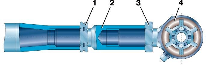
Rice. 5.3. Steering gear for UAZ-31512 family vehicles:
1 – steering linkage levers; 2 – transverse steering rod; 3 – bipod of the steering mechanism; 4 – bipod thrust; 5 – steering knuckle lever

Rice. 5.4. Steering gear for UAZ-3741 family vehicles:
1 – longitudinal steering rod; 2 – longitudinal steering rod lever; 3, 6 – steering linkage levers; 4, 7 – tie rod ends; 5 – transverse steering rod
The car's steering consists of a worm-roller steering mechanism with a steering wheel (Fig. 5.1, 5.2) and a steering gear (Fig. 5.3, 5.4).

Rice. 5.5. Steering mechanism type screw-ball nut-sector:
1 – steering housing; 2 – shaft sector; 3 – nut-rack; 4 – balls; 5,21,24 – retaining rings; 6,9,20,25 – protective covers; 7 – universal joint; 8 – bushing; 10 – cuff; 11 – propeller bearings; 12 – bolts securing the steering mechanism to the frame; 13 – adjusting shims; 14 – screw; 15 – bipod; 16 – lower crankcase cover; 17, 23, 26 – sealing rings; 18 – nut; 19 – washer; 22 – rollers; 27 – protective ring; 28 – sector shaft support ring; 29 – filler plug; 30 – ball guide groove; 31 – ball guide lining; 32 – drain plug; 33 – plug

Rice. 5.6. Power steering:
1 – nut; 2, 5, 6, 19, 21, 22, 35, 39 – sealing rings; 3 – glass; 4, 10 – thrust bearings; 7 – piston-rack; 8 – screw; 9 – crankcase; 11 – discharge hose fitting; 12 – drain hose fitting; 13 – sleeve; 14 – cuff; 15 – torsion bar; 16, 38 – pins; 17 – ball guide; 18 – balls; 20 – channel in the crankcase; 23 – bipod; 24 – bipod nut; 25 – protective bottom cover; 26 – retaining rings; 27 – adjusting washers; 28 – bipod shaft supports; 29 – rollers; 30 – bipod shaft; 31 – upper protective cover; 32 – rotor; 33 – protective cap; 34 – distributor housing; 36 – channel in the distributor housing; 37 – bolts securing the distributor housing to the crankcase
Some vehicles of the UAZ-31512 family are equipped with a steering mechanism of the screw-ball nut-sector type without hydraulic booster (Fig. 5.5) or with hydraulic booster (Fig. 5.6).
Maintenance steering controls differ only in the adjustment of the steering mechanisms.
Promptly tighten the bolts securing the steering gear housing to the frame side member, check the fastening of the steering rod pins, bipod and steering knuckle lever. Check the free play of the steering wheel, adjust the steering gear, lubricate the tie rod joints and add oil to the steering gear housing or oil reservoir (in the case of a power steering gear), according to the lubrication chart.
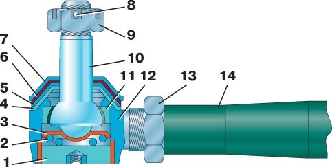
Rice. 5.7. Tie rod joint:
1 – plug; 2 – spring; 3 – heel; 4 – lower spherical washer; 5 – upper spherical washer; 6 – protective ring; 7 – spring cap; 8 – cotter pin; 9, 13 – nuts; 10 – ball pin; 11 – cracker; 12 – tip; 14 – traction
If a gap appears in the steering rod joints, screw plug 1 until it stops (Fig. 5.7), and then unscrew it 1/2 turn and seal it in this position.
Periodically check the tightness of the tie rod end nuts.
Do not allow gaps to appear in the conical joints of the levers and pins.
To remove them, unscrew the nut and tighten it until it stops.
Failure to tighten these connections promptly will cause wear on the conical holes in the arms, which will require parts to be replaced.
When servicing vehicles of the UAZ-31512 family, pay attention to the condition of the mounting of the bearings in the steering joint forks.
If radial play appears in the hinge (axial movement of the cross in the bearings), perform additional core drilling of the bearings in the fork ears. Perform the core in such a way as to prevent the bearing cup from being crushed.
The crosspiece bearings contain Litol-24 lubricant when assembled at the factory and do not need to be added during operation.
Maintenance of the power steering system consists of checking the tension of the pump drive belt, checking the tightness of the hoses and their connections, checking for leaks in the seals of the pump and steering mechanism, checking the level and changing the oil in the oil tank.
Checking the free play of the steering wheel
The condition of the steering mechanism is considered normal and does not require adjustment if the free play of the steering wheel in the straight-line position does not exceed 10 degrees, which corresponds to 40 mm when measured on the rim of the steering wheel.
If you have power steering, check the free play of the steering wheel when the engine is running in idle move, rocking the steering wheel in one direction or another until the front wheels begin to turn.
In the case of a steering mechanism without a hydraulic booster, check the free play by applying a force of 7.5 N (0.75 kgf) on the steering wheel rim in both directions. If the free play is more than specified, then before proceeding to adjust the steering mechanism, check the fastening of the steering mechanism, the condition of the steering rod joints, the condition of the steering column joint, the tightness of the bolts securing the hinge forks and the absence of play in the splined connection of the propeller shaft, the tightening of the bipod mounting nuts and lever, steering wheel mount.
Power steering pump drive belt tension
With normal belt tension, its deflection in the middle between the crankshaft and pump pulleys, when pressing the belt with a force of 39 N (4 kgf), should be 12–17 mm. If necessary, tension the belt by moving the pump along the bracket attaching it to the engine. To do this, loosen the bolts securing the pump to the bracket, move the pump with the tension screw until the belt is at normal tension and tighten the bolts securing the pump. Replace the belt if it is damaged or overstretched.
Checking the level and changing the power steering oil
When checking the oil level in the oil tank, the front wheels should be set straight.
Add oil to the level of the oil tank filler filter mesh or no more than 5 mm above it. The oil must be pre-filtered through a filter with a filtration fineness of no more than 40 microns.
All-season oil of grade "P" is used as the working fluid.
The volume of oil to be filled is 1.1 liters.
Every 100,000 km or 2 years of operation, replace the oil and filter in the oil tank.
Also change the oil when repairing or adjusting the steering mechanism.
Charging the system
1. Remove the oil tank cap, fill in oil until it appears above the filter mesh (no more than 5 mm).
2. Without starting the engine, turn the steering wheel or the input shaft of the mechanism from lock to lock until the air bubbles stop leaving the oil in the tank. Add oil to the tank. When bleeding, you should disconnect the bipod rod from the bipod or hang the front wheels.
3. Start the engine while adding oil to the tank.
Note If the oil foams heavily in the tank, which indicates air has entered the system, turn off the engine and let the oil sit for at least 20 minutes (until air bubbles leave the oil). Inspect the connection points of the hoses to the power steering system units and, if necessary, eliminate leaks.
4. Let the engine run for 15–20 seconds and bleed the power steering system to remove residual air from the steering mechanism by turning the steering wheel from lock to lock, without holding it in its extreme positions, three times in each direction.
5. If necessary, add oil to the tank.
6. Place the cap on the tank and tighten the cap nut by hand.
7. Attach the bipod rod, tighten and cotter the ball pin nut.
Maintenance of pump flow and safety valves
If the flow and safety valves become dirty, wash them.
For this:
1. Unscrew the plug located above the pump outlet.
2. Remove the spring and spool of the flow valve, and install the plug in place, which will prevent oil leakage.
3. Wash the spool and the safety valve, which is installed inside the spool.
4. Reassemble in reverse order.
Adjusting the worm-roller steering mechanism
The steering mechanism must be adjusted to eliminate the gaps that appear between the worm and the roller.
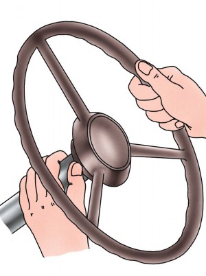
Rice. 5.8. Checking the axial clearance in the worm bearings
Start the adjustment by checking the axial clearance in the worm bearings.
To do this, wrap your palm around the column so that thumb touched the end of the steering wheel hub and turn the steering wheel in both directions at a certain angle (Fig. 5.8). When the worm bearings wear out, your finger will feel the axial movement of the steering wheel hub relative to the column tube. If there is no axial movement of the worm, then adjust only the engagement of the roller with the worm.
Adjusting the tightening of the worm bearings ) using gaskets 13 (see Fig. 5.1) installed between the crankcase and the lower cover of the steering gear housing, in the following order:
1. Remove the steering gear from the vehicle.
2. Drain the oil from the crankcase.
3. Secure the steering gear in a vice.
4. Unscrew nut 33 and remove lock washer 34 from adjusting screw 32.
5. Unscrew the bolts securing the side cover 37 of the crankcase.
6. Lightly hitting the end of bipod shaft 17 with a copper or aluminum drift, remove the bipod shaft along with the roller and cover and carefully remove gasket 38.
7. Unscrew the bolts securing the lower crankcase cover 12 and remove the cover.
8. Carefully separate and remove the thin paper gasket 13.
9. Reinstall the bottom cover, tighten the bolts and check the axial movement of the worm.
10. If the axial movement remains, remove the bottom cover again, remove the thick gasket, and install the previously removed thin gasket in its place. Do not remove more than one gasket
11. By rotating worm 11, finally check the tightness of bearings 8 and 14. If the worm roller bearings are correctly tightened, the force required to turn the steering wheel should be 2.2–4.5 N (0.22–0.45 kgf) (without installed bipod shaft).
Check the tightness of the bearings using a dynamometer (Fig. 5.9).

Rice. 5.9. Checking the tightness of the worm bearings using a dynamometer
Adjusting the engagement of the roller with the worm vehicles of the UAZ-31512 family ( Adjustment on vehicles of the UAZ-3741 family is carried out similarly) carry out in the following order:
1. Set the steering wheel to the position corresponding to the vehicle moving in a straight line.
2. Disconnect the steering rod from the bipod.
3. Unscrew nut 33 (see Fig. 5.1) and remove lock washer 34 from adjusting screw 32.
4. By turning adjusting screw 32 clockwise, eliminate the gap in the engagement.
5. Install the lock washer. If the hole in the washer does not line up with the pin, turn the adjusting screw so that the hole in the washer lines up with the pin.
6. Screw nut 33 onto the adjusting screw and, shaking it with your hand, steering bipod, check that there is no play in the engagement.
7. Check the force required to turn the steering wheel. The steering wheel should rotate freely from the middle position, corresponding to straight motion, with a force of 9–16 N (0.9–1.6 kgf) applied to the steering wheel. If there is no special device for checking the force required to turn the steering wheel, use a dynamometer.
8. Connect the rod to the bipod
Adjusting the steering mechanism type screw-ball nut-sector
To adjust the steering mechanism, remove it together with the bipod from the vehicle.
Secure the steering mechanism with the splined end of screw 14 (see Fig. 5.5) up, the axis of screw 14 should be in a vertical position.
1. Using a dynamometer, measure the turning torque of screw 14 in the middle and extreme positions of the sector shaft
2. The middle position of the sector shaft is found by turning the screw 2.5 turns from either extreme. To measure the turning torque of the screw in the extreme position of the sector shaft, it is necessary to move the sector shaft away from the stop in the extreme position by turning the screw 1/2 a turn and measure the torque value by rotating the screw one turn. If the bearings are tightened correctly and there is no gap in the engagement of the rack nut and the sector shaft, the torque of the shaft in the middle position of the sector shaft should be 1.6–2.5 N m (0.16–0.25 kgf m), in the extreme position of the sector shaft, the moment should decrease to 0.8–1.2 N m (0.08–0.12 kgf m).
3. If the torque of turning the screw in the extreme positions is less than specified, it is necessary to adjust the tightening of the bearings 11 of the screw.
Adjusting the tightening of screw bearings
1. Install the steering mechanism with the bottom cover 16 (see Fig. 5.5) up and secure in this position.
2. Unscrew the cover mounting bolts and remove cover 16.
3. Remove one of the thin gaskets 13 (0.05 mm thick).
4. Put the cover in place, tighten the bolts, turn the steering mechanism over with the splined end of the screw 14 up and again measure the turning torque of the screw in the extreme positions.
5. If the required torque value is not achieved, remove the 0.1 mm or 0.15 mm thick gasket in the same sequence, and replace the previously removed gasket. The steering mechanism is equipped with at least three shims with a thickness of 0.05 mm, and shims with a thickness of 0.1 mm, 0.15 mm and 0.5 mm can also be installed, the number of which is determined by the needs of the assembly. It is not recommended to remove more than one gasket with a thickness of 0.05 mm in the presence of gaskets of greater thickness.
6. Finally check the torque of the screw in the extreme positions of the sector shaft.
If, when checking the turning torque of the screw, it turns out that the moment in the extreme positions of the sector shaft corresponds to the recommended value, and the moment in the middle position of the sector shaft is lower than the recommended value, the engagement of the rack nut 3 and the sector shaft 2 should be adjusted.
An additional sign of the need to adjust the engagement can be a gap that is noticeable when the sector shaft is rocked by the bipod in the middle position of the sector shaft.
Gear adjustment perform in the following sequence:
1. If on the ring mechanism 28 (see Fig. 5.5) the sector shaft supports are locked by punching the collar into the crankcase hole, remove the plugs 33 holes and straighten the collar using a punch and a hammer, without using excessively strong blows. If the indicated rings are secured with screws, loosen them.
2. Remove protective covers 20 and 25. When locking the rings with a core, you must also remove the bipod.
3. Eliminate the gap in the engagement by turning the rings 28 of the sector shaft supports counterclockwise when viewed from the side of the sector shaft splines. In this case, the support rings of the sector shaft must rotate at the same angle.
4. Check the torque of the screw in the middle position of the sector shaft.
5. When the screw turning torque in the middle position reaches the recommended value, lock the sector shaft support rings by punching the collar into the crankcase holes or tightening the locking screws and locknuts.
6. Install protective covers 20 and 25, plugs 33, bipod. Pre-tighten the bipod fastening nut. Make the final tightening of the bipod nut after installing the steering mechanism on the vehicle and connecting the bipod rod to the bipod.
Adjusting the power steering mechanism
To adjust the steering gear, it must be removed from the vehicle.
For this:
1. Disconnect the pressure and drain hoses from the steering mechanism and secure the hoses in such a way as to prevent complete leakage of oil from the hydraulic system.
2. Unscrew the nut and remove the wedge screw from the hinge fork, remove the hinge fork from the mechanism.
3. Disconnect the bipod link from the bipod.
4. Unscrew the fastening bolts and remove the steering mechanism.
Adjusting the steering mechanism perform in the following sequence:
1. Secure the steering gear in a vice so that the discharge and drain holes are at the bottom. While turning the steering input shaft by hand, drain the oil from the mechanism.
2. Lightly pressing the input shaft along its axis with your hand, rock the bipod. If axial movement of the input shaft is felt, adjust the tension of the propeller bearings.
For this:
– using a punch and a hammer, carefully, without using excessively strong blows, straighten the collar of the glass 3 (see Fig. 5.6), fixed in the grooves of the crankcase wall 9;
– turning glass 3 clockwise, eliminate the play;
– check the turning torque of the input shaft, which should be no more than 3 N·m (0.3 kgf·m). Measure the torque over no more than one revolution of the input shaft from any extreme position;
– insert the edge of the glass into the grooves of the crankcase wall
3. If the axial movement of the rotor is not felt or is eliminated, and a gap is felt in the middle position of the bipod shaft when rocking the bipod, adjust the gearing.
For this:
– unscrew nut 24 and remove bipod 23;
– remove the upper 31 and lower 25 protective covers;
– remove the locking rings 26 and adjusting washers 27;
– straighten the adjusting washers;
– simultaneously turning the supports 28 of the bipod shaft counterclockwise (as viewed from the splined end of the bipod shaft), eliminate the gap in the engagement. Make the adjustment in the bipod shaft position corresponding to the middle position of the gear sector;
– check the turning torque of the bipod shaft, which should be within 35–45 N·m (3.5–4.5 kgf·m) when the bipod shaft passes through the middle position. If, after adjusting the bearing tension and gear clearance, the backlash cannot be eliminated, then the backlash is caused by wear of the ball screw. In this case, the steering mechanism must be repaired;
– install the adjusting washers, bend one of the tabs in both adjusting washers into the groove of the bipod shaft support and install the locking rings.
4. Install the steering gear on the car, install the bipod and tighten the bipod nut by hand.
5. Attach the propeller shaft fork, discharge and drain hoses, avoiding twisting or sharp bends, and fill the hydraulic system with oil (see above).
6. Attach the bipod rod, tighten and cotter the ball pin nut, tighten the bipod nut.
Repair
When repairing the steering, use the data in table. 5.1.
Removing and disassembling the tie rod do it in the following order:
1. Unsplit the nuts securing the steering linkage pins.
2. Unscrew the nuts and use a tool to press the pins out of the levers.
3. Remove spring caps 7, rubber protective rings 6 and spherical washers 4 and 5 from fingers 10 (see Fig. 5.7).
4. Secure the rod in a vice, unscrew the lock nuts 1 (Fig. 5.10) and 3 and unscrew the ends 4 and the adjusting fitting 2.
5. Unscrew the threaded plug (Fig. 5.7) of the tip and remove spring 2, heel 3, pin 10 and cracker 11.
Rice. 5.10. Tie rod end:
1 – nut with left-hand thread; 2 – adjusting fitting; 3 – nut with right-hand thread; 4 – tip
Rod assembly do in reverse order.
Replace the finger complete with a cracker. It is not recommended to replace only the pin, since the sphere of the cracker wears unevenly and when replacing one pin, it is not possible to achieve a good mating of the spheres of the pin and the cracker.
Before assembly, lubricate the hinge parts according to the lubrication chart. When installing a screw plug, screw it in until it stops, then unscrew it 1/2 turn and seal it in this position.
Removing, disassembling and assembling the bipod rod produced in the same way.
Tightening torques for main steering connections, N m (kgf m):
Steering wheel nut.....64–78 (6.5–8.0)
Bracket stud nuts (column mounting stepladders)......18–25 (1.8–2.5)
Nut securing the steering shaft joint forks.....20–25 (2.0–2.5)
Bolts securing the crankcase to the frame of cars of the family:
UAZ–31512.....55–78 (5.6–8.0)
UAZ–3741.....55–61 (5.6–6.2)
Bipod nut.....196–275 (20–28)
Steering rod lock nuts.....103–128 (10.5–13.0)
Ball pin fastening nut..... 49–69 (5–7)
Steering mechanism without power steering
Removing and disassembling the steering column Cars of the UAZ-31512 family should be carried out in the following order:
4. Unscrew the steering wheel mounting nut 2–3 turns and, using a puller (Fig. 5.11), loosen the steering wheel fastening on the steering shaft cone. Unscrew the steering wheel nut and remove the steering wheel.
5. Unscrew the nuts and remove the steering column mounting step and the rubber bushing.
6. Unscrew the nut and remove the upper steering column joint pinch bolt.
7. Remove the steering column.
8. Unscrew screw 27 (see Fig. 5.1) and remove bushings 26 and 28.
9. Remove the lower retaining ring 20, protective washer 21, spring 22 and release ring 23.
10. Remove the steering shaft 31, press out the bearings.
Disassemble the steering column only to replace worn bearings.
Reassemble and install the steering column in the reverse order

Rice. 5.11. Removing the steering wheel
Removing the steering mechanism from vehicles of the UAZ-31512 family without removing the steering column, do it in the following order:
1. Remove the steering column joint pinch bolt.
2. Unscrew the nut securing the steering gear bipod and remove the bipod (Fig. 5.12) using a puller.
3. Remove the bolts securing the steering gear housing to the frame side member.
4. Remove the steering gear and drain the oil
Removing the steering mechanism from vehicles of the UAZ-3741 family do it in the following order:
1. Remove the turn signal switch.
2. Disconnect the signal wire.
3. Remove the signal button and contact parts.
4. Unscrew the steering wheel mounting nut 2–3 turns and, using a puller (see Fig. 5.11), loosen the steering wheel fastening on the steering shaft cone. Unscrew the steering wheel nut and remove the steering wheel.
5. Unscrew the nuts and remove the steering column mounting step and the rubber bushing.
6. Disconnect the bipod link from the bipod.
7. Remove the steering gear housing mounting bolts.
8. Remove the steering mechanism along with the steering column.
On cars with a steering column with a cardan joint (see Fig. 5.2, a), removal of the steering mechanism is possible without removing the steering column (similar to removing the steering mechanism of cars of the UAZ-31512 family).
Rice. 5.2. Steering mechanism of cars of the UAZ-3741 family:
a – variant design – steering column with cardan joint; 1 – bipod; 2 – crankcase; 3 – bottom cover; 4 – adjusting shims for worm bearings; 5 – roller; 6 – worm; 7, 8, 29 – bearings; 9 – cork seal; 10 – filler plug; 11 – gasket; 12 – side crankcase cover; 13 – pin; 14 – lock washer; 15, 35 – bushings; 16 – bipod shaft; 17 – cuff; 18 – washer; 19 – nut; 20 – steering wheel; 21 – column; 22 – steering shaft; 23 – bipod shaft bearing; 24 – adjusting screw of the gap in engagement; 25 – cap nut; 26 – roller axis; 27 – oil seal; 28 – audio signal wire; 30, 39 – plastic bushings; 31 – screw; 32 – spacer sleeve; 33 – protective washer; 34 – hinge; 36 – retaining ring; 37 – spring; 38 – contact sleeve
Disassembling the worm-roller steering mechanism do it in the following order:
1. Disconnect the universal joint from the worm shaft (on vehicles of the UAZ-31512 family).
2. Unscrew the nut and remove the lock washer from the adjusting screw.
3. Remove the bolts securing the side crankcase cover.
4. Using a light blow with a copper or aluminum drift on the end of the bipod shaft, remove the bipod shaft along with the roller and cover and carefully remove the gasket.
5. By screwing the adjusting screw into the side cover of the crankcase, remove the side cover and the adjusting screw from the bipod shaft.
6. Unscrew the bolts securing the lower crankcase cover and remove the cover along with the gaskets, the outer race of the lower bearing and the cage with rollers.
7. Remove the shaft with the worm assembly and the separator with the rollers of the upper bearing from the crankcase. Press the outer ring of the upper bearing, the steering gear shaft collar, the bipod shaft collar and the bipod shaft bushing out of the steering gear housing only if they are replaced.
Disassembling the steering mechanism type screw-ball nut-sector do it in the following order:
1. Remove the protective covers and retaining rings of the sector shaft support rings on both sides.
2. Remove the plugs in the holes F 7 mm of the crankcase above the sector-shaft supports and straighten the shoulders of the supports or loosen the locking screws, as indicated in the subsection “Adjusting the gearing”.
3. Using a light blow with a copper or aluminum drift on the end of the sector shaft, first from the side of the upper support, and then from the side of the pin end, remove the support rings and the sector shaft.
4. Unscrew the bolts securing the lower crankcase cover and remove it along with the adjusting shims, the outer race of the lower propeller bearing and the ball cage.
5. Remove the screw assembly from the crankcase with the rack nut, inner rings of bearings and the separator with balls of the upper bearing. Remove the outer ring of the upper bearing of the propeller, the cuff of the propeller shaft, the sealing rings in the body and cover, the sealing and protective rings in the sector shaft supports only if it is necessary to replace them. Press out the inner rings of the bearings and remove the nut-rack with screws also only if it is necessary to replace the bearings and parts of the ball screw pair of the steering mechanism. Do not unnecessarily disassemble the rollers in the sector shaft support rings.
Assessment of the technical condition of parts.
After disassembly, thoroughly rinse and inspect each part.
If peelings of the hardened layer in the form of shells appear on the surface of the worm, screw, rack nut or sector shaft of the steering mechanism, as well as if they are significantly worn, replace the parts.
Replace the worm (screw) bearings with new ones if it is necessary to remove all adjusting shims to eliminate axial play or if the working surfaces of the rings and rollers (balls) are damaged.
If there are holes, cracks, dents on the working surfaces of the bipod shaft roller, or if there is play in the ball bearings or in the fit on the axle, then drill out the axle head, knock out the axle, and remove the roller. Insert the new roller and axle into the shaft groove.
It is allowed to fasten the old axle to the bipod shaft by electric welding - on the side of the drilled head, and the new axle - on both sides. At the same time, do not allow the roller to overheat.
Replace the sector shaft support rings if there are pits, dents or significant wear on the surfaces under the rollers.
Replace the bronze crankcase bushing if there is significant wear on one side. After pressing the new bushing into the crankcase, iron it with a brooch to a diameter of 35 +0.027 mm.
Assembling a worm-roller steering mechanism Proceed in reverse order, taking into account the following:
1. When replacing the worm, when pressing it onto the shaft, it is necessary that the high spline of the worm coincides with the keyway of the shaft. The discrepancy between the end of the shaft and the end of the groove on the worm should not exceed 0.25 mm.
2. The bipod shaft roller should rotate freely by hand. When installing into the crankcase, lubricate the cylindrical part of the bipod shaft and the roller with liquid lubricant. Lubricate cylindrical and tapered bearings, outer surfaces of the worm and oil seals with Litol-24 grease.
3. Tighten the worm bearings and adjust the engagement of the roller with the worm as indicated in the section “Adjusting the worm-roller steering mechanism.”
4. The runout of the shaft journal under the ball bearing of the steering column on the assembled steering system should not be more than 3 mm. When checking, the shaft assembly with the worm should easily rotate in the worm bearings (for vehicles of the UAZ-3741 family).
5. When installing the steering mechanism on vehicles of the UAZ-3741 family, first tighten the bolts securing the crankcase to the frame side member, and then secure the column. In this case, first select the required number of adjusting shims installed between the rubber bushing and the column mounting bracket to prevent bending of the shaft.
Assembly of the steering mechanism type screw-ball nut-sector carry out in the reverse order of disassembly, taking into account the following:
1. Assemble the screw and the mating nut-rack with balls 7.144–40 GOST 8722–81 of only one group and from one batch.
2. The bolts fixing the gutter cover must be tightened to a torque of 8–10 N·m (0.8–1.0 kgf·m). One of the tabs of the lining, which coincides with the edge of each bolt, must be bent to the edge of the bolt after tightening.
3. The rotation of the screw in the rack nut should be smooth without jamming or jerking. The torque required to turn the screw should be 0.3–0.5 N·m (0.03–0.05 kgf·m). Check the torque after turning the rack nut twice along the entire length of the screw.
4. Adjust the preload of the propeller bearings using adjusting shims before installing the sector shaft, and the number of shims with a thickness of 0.05 mm should be at least three. Axial and radial movements of the screw are not allowed. Control its absence with a force of 49–78 N·m (5–8 kgf·m).
5. When installing the sector shaft, the middle tooth of the sector must fit into the middle cavity of the rack nut.
6. Install the sector shaft supports by smoothly, without distortions, pressing them into the crankcase holes, while the support rollers should be of the same group, and to prevent them from falling out, one plastic insert should be installed between them. When installing the sector shaft supports, the grooves on the outer ends of the support rings should be opposite the holes in the housing Zh 7 (for plugs), while the mark on the ring should be as far away from the gearing as possible.
7. After installing the retaining rings, check the axial movement of the sector shaft, which should be within 0.02–0.1 mm with a force of 15–20 N (1.5–2.0 kgf).
8. Adjust the engagement of the rack nut and the sector shaft by simultaneously turning the sector shaft support rings in the crankcase holes clockwise, as viewed from the splined end of the sector shaft. In this case, the grooves on the outer ends of the rings, intended for their rotation, must be located in the same plane.
9. After completing the engagement adjustment, fix the position of each sector shaft support, as indicated in the “Adjusting the engagement” subsection.
10. Before installing the protective plastic covers, lubricate the surfaces of the parts they cover with Litol-24 lubricant.
Removing the steering gear do it in the following order:
1. Disconnect the hoses from the steering mechanism by unscrewing the bolt fittings and secure the hoses so as to prevent complete leakage of oil from the hydraulic system or drain the oil into a clean container.
2. Unscrew the nut of the bolt securing the universal joint fork, remove the bolt, and remove the fork from the output shaft of the mechanism.
3. Unscrew and unscrew the nut securing the bipod rod hinge pin to the bipod, remove the pin from the bipod hole.
4. Unscrew the steering gear mounting bolts and remove the steering gear.
Dismantling the power steering mechanism
1. Drain the oil from the mechanism by turning the input shaft from stop to stop.
2. Using a puller, remove the bipod from the bipod shaft.
3. Remove the upper and lower protective covers of the bipod shaft supports.
4. Remove the retaining rings of the bipod shaft supports and the lock washers.
5. Using a gentle press, press out the bipod shaft together with the upper support, without completely removing the bipod shaft from the lower support.
6. Remove the upper support with rollers from the bipod shaft, without scattering the rollers.
7. By smoothly pressing the press on the upper end of the bipod shaft, press out the lower support of the bipod shaft.
8. Remove the lower support with rollers from the bipod shaft, remove the bipod shaft.
9. Remove the sealing rings for the bipod shaft supports from the grooves in the crankcase.
10. Remove the bolts securing the distributor housing.
11. Carefully, without distortion, remove the distributor housing.
12. Remove the screw with the hydraulic distributor and the piston rack from the crankcase.
13. Remove the bearing cup with the bearing and nut from the crankcase.
Disassembling the Ball Screw
1. Bend the petals of the ball guide trim from the edges of the bolts.
2. Unscrew the bolts securing the ball guide lining.
3. Remove the ball guide from the piston rack.
4. Turn the piston rack over with the holes for the ball guide down and, turning the screw by hand, pour out the balls.
5. Remove the screw from the piston rack.
Dismantling the hydraulic distributor
1. Carefully press out the sleeve pin and torsion bar pin.
2. Using a special tool, remove the rotor with sleeve and torsion bar from the screw.
3. Carefully remove the sleeve from the rotor.
4. Remove the torsion bar from the rotor. Remove the sealing rings and seals installed in the distributor body and in the piston rack only when replacing them.
Grade technical condition details
After disassembly, rinse thoroughly and dry compressed air and inspect the details.
If peelings of the hardened layer in the form of shells appear on the working surface of the screw, piston rack, bipod shaft, bipod shaft supports or rolling bodies of bearings, as well as when they are significantly worn, replace the parts.
Replace the bipod shaft if its splines are twisted.
Replace the rubber O-rings if there is damage or a change in cross-sectional shape (the rings should be round) visible to the naked eye.
When replacing a screw or piston rack, parts must be replaced only with parts from the same group. The group number is marked on the end of the screw and the piston rack.
The hydraulic booster parts (rotor, sleeve and torsion bar) are selected individually at the manufacturer, and therefore can only be replaced as a set. In this case, it is necessary to adjust the hydraulic center on a special stand. The shaft supports must be replaced together with the rollers.
The power steering mechanism is assembled in the reverse order of disassembly, taking into account the following:
Ball Screw Assembly.
To assemble the ball screw, balls with a diameter of 7.144 ±0.014 mm are used, sorted into seven groups by diameter every 0.004 mm. To assemble, all balls must be in the same group. To facilitate assembly, use a dispenser tube (tube 10x1 mm, length 275 mm).
1. Insert the screw into the hole in the piston rack and align the first turn of the screw groove with the hole in the piston rack for the ball guide closest to the screw flange.
2. Insert the dosing tube filled with balls into the hole of the ball guide so that the balls begin to fill the screw channel.
3. To fill the screw channel, smoothly turn the screw counterclockwise until the first ball appears in the second hole for the ball guide.
4. Fill the ball guide groove with the remaining balls. To prevent the balls from scattering, thickly lubricate the groove with Litol-24 grease.
5. Insert the groove filled with balls together with the second groove into the hole under the ball guide in the piston rack.
6. While holding the ball guide from falling out, check the turning torque of the screw, which should be 0.5–0.8 N·m (0.05–0.08 kgf·m). Rotation should be smooth, without jerking or jamming. If the torque is greater or less than required, replace the entire set of balls with a set of smaller or larger diameter, respectively. Mixing balls of different size groups is not allowed.
7. Install the ball guide lining, tighten the bolts securing it and lock them by bending the lining tab onto the edge of each bolt.
Installation of fluoroplastic sealing rings
Fluoroplastic sealing rings are used to seal moving joints: sleeve-distributor housing, rack-piston-crankcase, screw-rack-piston. In the bipod shaft supports, a protective fluoroplastic ring is used together with a rubber one. Re-installation of fluoroplastic rings is not allowed. The inner rings are installed with preliminary deflection inward, the outer ring with preliminary stretching on a conical mandrel to a size sufficient for installation. After installation, the rings must be calibrated (precipitated) with special mandrels and held on the mandrel for 30 minutes (Table 5.2).
Assembling the steering mechanism from subassembled units
1. In cup 3 (see Fig. 5.6) install bearing disk 4, a separator with rollers and a ring.
2. Install rubber o-ring 2 and nut 1 into the crankcase so that the protrusion of the nut coincides with the groove on the bottom of the crankcase.
3. Screw the glass into the nut 2–3 turns.
4. Install the piston rack assembly with screw, rotor and liner in the crankcase so that the protrusion of the screw fits into the hole in the bearing ring, and the teeth of the piston rack are parallel to the axis of the bipod shaft.
5. Install roller bearing 10 onto the screw.
6. Install the distributor housing 34, secure it with bolts 37.
7. Adjust the tension in the propeller bearings (see subsection “Adjusting the power steering mechanism”).
8. Rotating the input shaft and holding the piston rack from turning, install the piston rack so that the middle depression of the rack is opposite the center of the hole for the bipod shaft. Install rubber rings 21.
9. On bipod shaft 30, install support 28 with rollers 29 and sealing rings 22 so that the mark on the support is located opposite the middle tooth of the bipod shaft sector.
10. Insert the bipod shaft with the support into the crankcase so that the middle tooth of the sector fits into the middle cavity of the rack and press in the support.
11. Carefully, preventing the rollers from scattering, press in the second bipod shaft support.
12. Adjust the engagement of the sector of the teeth of the bipod shaft and the rack (see paragraph 3 of the subsection “Adjusting the power steering mechanism”).
An integral part of any vehicle is the steering control (RU), which ensures the safety of movement in the vehicle, changes the direction of movement, and also performs various maneuvers. On a UAZ Patriot SUV with hydraulic booster, the power steering system includes: a steering column, a steering wheel, a pair of steering rods, steering knuckles, and ball joints.
The SUV has a steering column in which there is a control shaft with two bearings. Thanks to the driveshaft, torque is transmitted from the steering wheel to the steering mechanism; the driveshaft itself consists of hinges and a sliding fork.
The UAZ Patriot steering column is attached to the steering wheel on the shaft splines, and secured to the shaft with a nut; the column also has a mechanism with which you can adjust the tilt angle. The entire control mechanism is located in the engine compartment, the crankcase of which is secured to the frame with bolts.

An important part of the control system is the steering linkage, which includes:
- Bipod;
- Bipod traction;
- Steering linkage rod which is adjustable in length;
- Tie rod ends;
- Steering knuckle lever;
- Rounded fist;
- Ball pin.

Steering gear
Over time, it happens that the UAZ Patriot steering wheel begins to malfunction, the main cause being the failure of the hydraulic booster or gearbox. Signs indicating that adjustment or replacement are required are as follows:
- There are squeaks and extraneous noises when driving;
- The steering wheel does not rotate evenly;
- There is jamming or jamming when the steering wheel rotates;
- There is play on the gearbox.
Adjusting the gearbox is not a complicated procedure, and you can do it yourself; to do this, you need to screw the bolt in such a way that there is maximum tension, then it is fixed in this position, after this procedure the steering wheel will begin to rotate tighter. If adjustment cannot be made, the hydraulic booster must be replaced.
Adjustment
To carry out setup work, you need to prepare all the necessary tools:
- Pliers to loosen the nuts;
- Set of wrenches;
- T-30 star tip;
- WD-40 lubricant.
After the entire instrument is prepared, you can proceed to adjusting the amplifier:

After the work is completed, you need to check that the bipod moves smoothly without jamming; a slight play is allowed. Then all the tips are installed in place and the operation of the mechanism is checked while moving.
Repair
There is a weak point in the steering column housing of the UAZ Patriot SUV, this is the thread where the bolt is screwed in, and during adjustment the integrity of the thread may be compromised, this is due to low quality metal The problem is solved in the following way:

After this procedure, you can make the necessary adjustments.
Steering column switches
For the convenience of performing certain manipulations, the car has special switches that are located under the steering wheel.

The steering column switches of the UAZ Patriot have a design consisting of two switches, in the form of a pair of plastic levers located under the steering column. The device located on the left side is responsible for:
- The work of the right turn signal;
- Operation of the left turn signal;
- Turning high and low beam on and off;
- Possibility of flashing high beams.
These functions are very important when driving a car, and moving without them vehicle forbidden. The right steering column switches are responsible for:
- Switching the speed of the wipers;
- Simultaneous activation of the wipers and windshield washer;
- Turning on the rear wiper;
- Simultaneous activation of the rear washer and wiper.
Of course, the functionality of the second lever is less important, but movement in rainy weather or snow will be difficult.
Useful video
We recommend watching the video:
To summarize, we can conclude that this mechanism must always be in good condition, otherwise it becomes unsafe to drive a car. In case of any malfunctions, all repair work can be done independently.
If slight motion appears in the conical joints of the levers and fingers, it should be eliminated in a timely manner. To do this, you need to unscrew the nut and tighten it until it stops. Failure to tighten these connections promptly will cause wear on the conical holes in the arms, which will require parts to be replaced.
Once a year, check that the steering column is correctly attached to the body brace bracket. To do this, you need to unscrew the stepladder nuts, tighten the bolts securing the crankcase to the frame longitudinal beam and specify the number of adjusting shims between the bracket and the rubber bushing of the steering column so that when tightening the stepladder nuts there is no bending of the shaft.
Adjusting the steering mechanism of UAZ-469 and UAZ-469B.
It is produced to eliminate gaps in the engagement of the worm with the roller that appear during vehicle operation. The working pair of the steering mechanism is designed in such a way that when the roller position corresponds to the vehicle moving in a straight line, the engagement gap is practically equal to zero. As the wheel turns in one direction or another, the engagement gap gradually increases, reaching its greatest value in the extreme positions of the roller.
The condition of the steering mechanism is considered normal and does not require adjustment if the free play of the steering wheel in the straight-line position does not exceed 10 degrees, which corresponds to 40 mm when measured on the rim of the steering wheel. If the steering wheel play is more than specified, then before you begin adjusting the steering mechanism, you need to make sure that the crankcase mounting bolts are tightly tightened and that the drive joints are in good condition.
Adjustment should begin by checking the axial clearance in the worm bearings. To do this, it is enough to grasp the column so that your thumb touches the end of the steering wheel hub and turn the steering wheel in both directions at a certain angle. When the worm bearings wear out, the axial movement of the steering wheel hub relative to the pipe will be felt with your finger. If there is no axial movement of the worm, it is only necessary to adjust the engagement of the roller with the worm.
Adjusting the tightening of the worm bearings of the steering mechanism of UAZ-469 and UAZ-469B.
This is done using gaskets installed between the crankcase and the lower cover of the steering gear housing, in the following sequence:
— Remove the steering mechanism from the car, drain it from the crankcase. Clamp the steering gear in a vice, unscrew the cap nut and remove the lock washer from the adjusting screw.
— Unscrew the bolts securing the side crankcase cover. Using a light blow with a copper or aluminum drift on the end of the bipod shaft, remove the bipod shaft along with the roller and cover, and carefully remove the gasket.
— Remove the lower crankcase cover, carefully remove the thin paper gasket, replace the lower cover, tighten the bolts and check the axial movement of the worm. If the axial movement remains, remove the bottom cover again, remove the thick gasket, and install the previously removed thin gasket in its place. Do not remove more than one gasket.
— Rotate the worm to finally check the tightness of the bearings. When the worm bearings are properly tightened, the force required to rotate the steering wheel should be 0.22-0.45 kgf without the bipod shaft installed. The tightness of the bearings is checked using a dynamometer, hooking it onto a spoke at the wheel rim.
Adjusting the engagement of the roller with the worm of the UAZ-469 and UAZ-469B steering mechanism.
The engagement of the roller with the worm can be adjusted without removing the steering mechanism from the vehicle. To do this you need:
— Set the steering wheel to the position corresponding to the vehicle moving in a straight line. Disconnect the tie rod from the bipod, unscrew the cap nut and remove the lock washer from the pin.
— Rotate the adjusting screw clockwise to eliminate the gap in the engagement and install the lock washer. If the hole in the washer does not line up with the pin, turn the adjusting screw so that the hole in the washer lines up with the pin.
— Screw the cap nut onto the adjusting screw and, shaking the steering arm with your hand, check for any play in the engagement. Then check the force required to rotate the steering wheel. The steering wheel should rotate freely from the middle position, corresponding to straight motion, with a force of 0.9-1.6 kgf applied to the steering wheel.