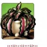
Do-it-yourself models of military equipment: a step-by-step description. Katyusha - a unique combat vehicle of the USSR How to make a Katyusha car out of cardboard
Model scale 1:25.
REACTIVE VOLVO FIRE SYSTEM BM-13 "KATYUSHA" ON THE CHASSIS.
"Katyusha" is the unofficial collective name for the BM-8 (82 mm) and BM-13 (132 mm) mobile rocket launchers. Such installations were actively used by the USSR during the Second World War.
Back in 1916. combat rocket on smokeless powder (a prototype of a late rocket) was invented by Ivan Platonovich Grave. In 1924 he received patent No. 122 for such a rocket charge. Further work on the creation of rockets on smokeless powder continued until the Great Patriotic War.
The development team included Sergei Korolev. In March 1941, successful field tests of the BM-13 installations with the M-13 projectile were carried out, and on June 21 a decree was signed on their serial production. On the night of June 30, 1941, the first two BM-13 combat launchers were assembled at the Komintern plant in Voronezh. Initially, they were mounted on the ZIS-5 chassis, but the use of such a chassis was considered unsuccessful, and it was replaced by the ZIS-6. Subsequently, BM-13 (BM-13N) were installed only on Studebaker (Studbacker-US6). experimental artillery battery of seven vehicles under the command of Captain I. Flerov, it was first used against the German army at the railway junction of the city of Orsha on July 14, 1941. The first eight regiments of 36 vehicles each were formed on August 8, 1941. An improved modification of the BM-13N was created in 1943, and about 1800 of these guns were manufactured by the end of World War II. Range - about 5 km.
The weapon was inaccurate, but very effective in massive use. The emotional effect was also important: during the salvo, all missiles were fired almost simultaneously - in a few seconds, the territory in the target area was literally plowed up by heavy rockets. At the same time, the deafening howl that the rockets raised during the flight literally drove me crazy. Those who did not die during the shelling often could no longer resist, as they were shell-shocked, stunned, and completely psychologically depressed. The mobility of the installation made it possible to quickly change position and avoid an enemy retaliatory strike.
Each car had a box of explosives and fuses. In the event of a risk of equipment being captured by the enemy, the crew was obliged to blow it up and thereby destroy the rocket systems.
The name "Katyusha" comes from the marking "KAT" ("Kostikova automatic thermite") on used incendiary rockets. And since the appearance of weapons in combat units coincided with the time of the popularity of the song "Katyusha", this name stuck.
We propose to build a model of the guards mortar BM-13 "Katyusha" on the platform at Studebaker (Studbacker-US6).
Specifications 
Engine - 6-cylinder, in-line.
Working volume -5240 cm Z.
Power -95 hp at 2500 rpm.
Load capacity -2.5 t.
Weight -4850 kg.
Speed -72 km/h.
Rocket M-13
Caliber, mm -132
Projectile weight, kg -42.3
Warhead mass, kg -21.3
Mass of explosive, kg -4.9
Firing range - maximum, km -8.47
Volley production time, sec 7-10.
Assembly instructions

1. Frame
The frame is assembled according to the scheme of parts 1-6. The folds are marked in gray. With the help of part 7, we glue the front bumper 9 and tow hooks 8, we assemble the back part from parts 10-15, part 13 is folded into a tube. For convenience, you can put a strip of cardboard 1 mm thick. in item 10.
Now you can assemble the pendant. First, three gearboxes are assembled from parts 30-36. Then, an axis 29, 69 and 108 is threaded through each. Then, using the crosses 50, the cardan shafts 51,70 and 71 are glued. It is more convenient to glue the crosses 50 if you first insert a part cut out of cardboard in the form of a cross. A transfer case is assembled from parts 72-1 and 72-2. A gearbox is assembled from parts 72-4 and 72-8 and glued to transfer case. Two rear axles with the help of part 66 they are glued to the frame, to part 2 and with the help of springs. The rear springs are assembled from strips 21 which are pre-folded in half, glued together and then glued together. After the package of springs is assembled, they must be given a semicircular shape in place. Instead of parts 25 and 26, you can use a toothpick.
2. wheels
Rear wheel rims are assembled from parts 203-206. Separately, we cut out the nuts 90 and glue them to the disk. Then we assemble the tire from parts 209-212. After assembly, the wheels are glued to axles 29 and 69.
The rims for the front wheels are assembled a little differently if you want to make them swivel. Part 208 is added on the front disks. The turning mechanism is assembled as follows: part 95 is rolled up into a ring and part 92 is inserted inside and fixed with part 94. Part 92 must rotate freely inside part 95. Then part 92 is glued to axis 108. Part 102 is glued inside the disk and item 99 is glued to it. After that, a tire is put on the disk. The order of further assembly is clear from the diagram.
3. Engine
It is better to start assembling the engine from body 111. Then it is glued to it optional equipment. To facilitate the gluing of part 112, a part cut out of cardboard, 1 mm thick, is glued inside. The remaining parts are glued in numerical order. After the engine, we assemble a radiator from parts 137-140. After assembly, the radiator and the engine are glued to the frame - the engine to part 5, and the radiator using part 141. After that, the radiator is glued to the engine using a tube glued from parts 142-146.
4. Cabin
First, we assemble the cabin interior. First we assemble the dashboard 180, which we glue to the front wall 186, and the floor 185 to it. We assemble the steering wheel 192 and the steering shaft 192-1. We fold the levers 194 in half and glue them together, we do the same with the pedals 195. Glue the finished pedals and levers according to the diagram. Lastly, we glue the seat (198-199) and the cabin interior is ready. Now we proceed to the outer skin of the cabin. The cab roof is assembled from parts 149-150. The ceiling 149-1 is glued to it from the inside. Then the back wall 148 and the side walls 160. The doors are folded and glued together. Hinges are glued between the halves of the doors. We glue the glasses cut out of the transparent film according to the patterns on last page and glue the wipers 197. Then we assemble the hood. The front wing is glued from part 182. From the wrong side, part 182-1 is glued. We glue the side wall 181 to it. We assemble the hood cover 180 according to the scheme and glue it in place. We glue two headlights 201 and one smaller one 202, which is located on the spruce side, and glue the grille 200. Glue the gas tank 214-216 behind the cab.
5. Launcher
Assembly of the launcher begins with the assembly of the base 218, which is attached to the vehicle frame with the help of parts 217. We glue control mechanisms 221-226 and 227-231 to the front. We collect guides for rockets. They are in three parts. Details 253 and 253-1 are bent to form an inverted letter P and glued together, then holes are cut into them, then strips 254 are glued on top and bottom. Guides are connected to each other using parts 257 rolled up with a tube. According to the scheme, we assemble a tubular structure, with the help of which we glue the guides to the base of the launcher. Parts for gluing are pre-formed on a mandrel with a diameter of 2 mm. and glue the launcher to the frame to parts 217.
But our toy army also needs equipment to transport foot soldiers and support the offensive with armored vehicles. We are now going to fill this gap. Today we have to learn how to make machines from matchboxes.
For work, we need several empty matchboxes, cardboard, an awl, a knife, PVA glue, scissors, a ruler, compasses and a simple pencil.
We also need to make our empty pen refills and insulated aluminum wire.
Well then, let's get to work. Take and remove the box from it. In the box itself, make side cuts according to the dimensions indicated in Figure 1a. and fold it up at a slight angle. The part that is shaded is to be cropped. Insert the box back into the box. We got the future cabin of the car.
Now take another box and cut its lid in half. Cut the removed one according to the dimensions indicated in the figure (Fig. 1b). Insert both parts of the cut box into the half of the box on both sides. Glue the resulting part to the cabin (Fig. 1c). Cut out two benches from the second half of the box (Fig. 1d) and fix them in the body with glue.
Next, we will make the chassis of the car. and with a compass draw on it twelve circles with a diameter of twenty millimeters (Fig. 1e). The circles should be cut out and glued together in four pieces (Fig. 1e). Paste the resulting wheels with prepared colored paper, as shown in the figure (Fig. 1g, Z.).
Now take the rods from fountain pens and make two axles of wheelsets out of them (Fig. 1k). Pierce all the wheels with an awl in the center and put them on the resulting axles. To prevent the wheels from flying off the axle, secure them with pieces of insulation from aluminum wire, pulling it gently with a knife.
Now we need to make bearings so that the wheelsets spin freely, and our homemade car can drive. We make bearings from cardboard (Fig. 1i). Bend the part along the dash-dotted lines in the form of a triangle (Fig. 1l), insert the wheels there and glue it to the bottom of the car. That's it, our matchbox car is ready to transport soldiers. You can make any number of such cars, as long as there are enough boxes.
To make an armored personnel carrier from matchboxes, you need to carefully consider Figure 2. Its device differs from a car only in that those boxes that are intended for making a hood (Fig. 2a, b) and making a tower (Fig. 2d, e) are cut obliquely and .
![]()
After you assemble the hood (Fig. 26), the body of the armored personnel carrier (Fig. 2c), as well as the turret (Fig. 2e), you need to cut out several round side and upper rectangular hatches for the turret (Fig. 2g). We will also make motor blinds (Fig. 2h).
The machine-gun barrel can be carefully rounded with a knife (Fig. 2f). Make a thickening by wrapping the base of the barrel with a thin copper wire, and glue it with a strip of colored paper. Now take the metal tip of the rod and pre-pierce a hole in the thickening of the machine gun with an awl, attach it to the tower by inserting it into the tower hole pierced with the same awl.
Figures 3 and 4 show how to make a Katyusha and a rocket launcher. The principle of their manufacture is the same as that of the machines described above. They are similar to trucks, but instead of a body they have special platforms (Fig. 3e and 4d), consisting of two parts. One part is made from the lid of the box (bottom part).

For "Katyusha" it is made rotary. It turns with the help of a round piece, which can be made from a piece or folded paper. One end of the tube is fixed at the bottom of the platform (Fig. 3f), its other end is inserted into the hole “o” of the second platform, which remains motionless (Fig. 3h).
To the inclined part of the platform (d), glue the next part (e), as shown in the figure (Fig. 3f).
We make Katyusha barrels in the amount of six pieces using a pencil, winding glued paper strips around it. Now you need to fix the trunks three pieces in a row on the part (d.) (Fig. 4)

The platform, or rather, its upper part (c) rocket launcher done a little differently. In the middle of the box, a longitudinal incision is made, which bends inward and is fixed with a clerical bracket. Then the upper honor is glued to the bottom of the site (Fig. 4d).
Glue the entire platform assembly in the back of the Katyusha. We do the same for the rocket launcher.
For a rocket launcher. Make its body as follows: wind a paper strip around a pencil (Fig. 4b) and glue its edge. Make the warhead and stabilizers as shown in the figure (Fig. 4e, f). It remains to glue them to the rocket body and fix them in the recess of the rocket platform.
All models made by us military equipment, can be painted with paints or pasted over with colored paper.
Our army has grown powerful armored vehicles, which we made with our own hands from ordinary matchboxes.
Soviet jet system salvo fire"Katyusha" is one of the most recognizable symbols of the Great Patriotic War. In terms of popularity, the legendary Katyusha is not much inferior to the T-34 or PPSh assault rifle. Until now, it is not known for certain where this name came from (there are numerous versions), the Germans called these installations "Stalin's organs" and were terribly afraid of them.
"Katyusha" is the collective name of several rocket launchers times of the Great Patriotic War. Soviet propaganda presented them as exclusively domestic "know-how", which was not true. Work in this direction was carried out in many countries and the famous German six-barreled mortars are also MLRS, however, of a slightly different design. Rocket artillery was also used by the Americans and the British.
Nevertheless, the Katyusha became the most efficient and most mass-produced vehicle of its kind in World War II. BM-13 is a real weapon of Victory. She took part in all significant battles on Eastern Front, clearing the way for infantry formations. The first volley of Katyushas was fired in the summer of 1941, and four years later, BM-13 installations were already shelling besieged Berlin.
A bit of history of the BM-13 "Katyusha"
Several reasons contributed to the revival of interest in rocket weapons: firstly, more advanced types of gunpowder were invented, which made it possible to significantly increase the range of rockets; secondly, rockets were perfect as weapons for combat aircraft; and thirdly, rockets could be used to deliver poisonous substances.
The last reason was the most important: based on the experience of the First World War, the military had little doubt that the next conflict would certainly not do without war gases.
In the USSR, the creation missile weapons began with the experiments of two enthusiasts - Artemiev and Tikhomirov. In 1927, smokeless pyroxylin-TNT gunpowder was created, and in 1928, the first rocket was developed that managed to fly 1300 meters. At the same time, the targeted development of missile weapons for aviation began.
In 1933, experimental samples of aviation rockets of two calibers appeared: RS-82 and RS-132. The main drawback of the new weapon, which did not suit the military at all, was their low accuracy. The shells had a small tail, which did not go beyond its caliber, and a pipe was used as guides, which was very convenient. However, to improve the accuracy of the missiles, their plumage had to be increased and new guides had to be developed.
In addition, pyroxylin-TNT gunpowder was not very well suited for the mass production of this type of weapon, so it was decided to use tubular nitroglycerin gunpowder.
In 1937, they tested new missiles with increased plumage and new open rail-type guides. Innovations significantly improved the accuracy of fire and increased the range of the rocket. In 1938, the RS-82 and RS-132 rockets were put into service and began to be mass-produced.
In the same year, designers were given new task: create a reactive system for ground forces, taking as a basis a 132 mm caliber rocket.
In 1939, the 132-mm high-explosive fragmentation projectile M-13 was ready, it had a more powerful warhead and an increased flight range. It was possible to achieve such results by lengthening the ammunition.
In the same year, the first MU-1 rocket launcher was also manufactured. Eight short guides were installed across the truck, sixteen rockets were attached to them in pairs. This design turned out to be very unsuccessful, during the volley the car swayed strongly, which led to a significant decrease in the accuracy of the battle.
In September 1939, tests began on a new rocket launcher, the MU-2. The three-axle truck ZiS-6 served as the basis for it, this machine provided combat complex high maneuverability, allowed to quickly change positions after each volley. Now guides for missiles were located along the car. In one volley (about 10 seconds), the MU-2 fired sixteen shells, the weight of the installation with ammunition was 8.33 tons, and the firing range exceeded eight kilometers.
With this design of the guides, the rocking of the car during the salvo became minimal, in addition, two jacks were installed in the rear of the car.
In 1940, state tests of the MU-2 were carried out, and it was accepted into service under the designation "BM-13 rocket launcher".
The day before the start of the war (June 21, 1941), the USSR government decided to mass-produce BM-13 combat systems, ammunition for them, and form special units for their use.
The very first experience of using the BM-13 at the front showed their high efficiency and contributed to the active production of this type of weapon. During the war, Katyusha was produced by several factories, and mass production of ammunition for them was launched.
Artillery units armed with BM-13 installations were considered elite, immediately after the formation they received the name of the guards. The reactive systems BM-8, BM-13 and others were officially called "guards mortars".
The use of BM-13 "Katyusha"
The first combat use of rocket launchers took place in mid-July 1941. Orsha, a large junction station in Belarus, was occupied by the Germans. It has accumulated a large number of military equipment and manpower of the enemy. It was for this purpose that the battery of rocket launchers (seven units) of Captain Flerov fired two volleys.
As a result of the actions of the artillerymen, the railway junction was practically wiped off the face of the earth, the Nazis suffered severe losses in people and equipment.
"Katyusha" was used in other sectors of the front. New soviet weapons was a very unpleasant surprise for the German command. Especially strong psychological impact the pyrotechnic effect of the use of shells on the Wehrmacht military personnel: after the Katyusha salvo, literally everything that could burn was burned. This effect was achieved through the use of TNT checkers in the shells, which, during the explosion, formed thousands of burning fragments.
Rocket artillery was actively used in the battle near Moscow, Katyushas destroyed the enemy near Stalingrad, they were tried to be used as anti-tank weapons on the Kursk Bulge. To do this, special recesses were made under the front wheels of the car, so the Katyusha could fire direct fire. However, the use of the BM-13 against tanks was less effective, since the M-13 rocket was high-explosive fragmentation, and not armor-piercing. In addition, "Katyusha" has never been distinguished by high accuracy of fire. But if her projectile hit the tank, all the attachments of the vehicle were destroyed, the turret often jammed, and the crew received a severe shell shock.
Rocket launchers were used with great success until the Victory itself, they took part in the storming of Berlin and other operations of the final stage of the war.
In addition to the famous BM-13 MLRS, there was also the BM-8 rocket launcher, which used 82 mm caliber rockets, and over time, heavy rocket systems appeared that launched 310 mm caliber rockets.
During Berlin operation soviet soldiers actively used the experience of street fighting, which they received during the capture of Poznan and Königsberg. It consisted in firing single heavy rockets M-31, M-13 and M-20 direct fire. Special assault groups were created, which included an electrical engineer. The rocket was launched from machine guns, wooden caps, or simply from any flat surface. The hit of such a projectile could well destroy the house or guaranteed to suppress the enemy's firing point.
During the war years, about 1400 BM-8 installations, 3400 BM-13 and 100 BM-31 installations were lost.
However, the history of the BM-13 did not end there: in the early 60s, the USSR supplied these installations to Afghanistan, where they were actively used by government troops.
Device BM-13 "Katyusha"
The main advantage of the BM-13 rocket launcher is its extreme simplicity both in production and in use. The artillery part of the installation consists of eight guides, a frame on which they are located, swivel and lifting mechanisms, sights and electrical equipment.
The guides were a five-meter I-beam with special overlays. In the breech of each of the guides, a locking device and an electric fuse were installed, with which a shot was fired.
The guides were mounted on a swivel frame, which, using the simplest lifting and turning mechanisms, provided vertical and horizontal aiming.
Each Katyusha was equipped with an artillery sight.
The crew of the car (BM-13) consisted of 5-7 people.
The M-13 rocket projectile consisted of two parts: a combat and a jet powder engine. Warhead, in which there was an explosive and a contact fuse, is very reminiscent of the warhead of a conventional high-explosive fragmentation projectile.
The powder engine of the M-13 projectile consisted of a chamber with a powder charge, a nozzle, a special grid, stabilizers and a fuse.
The main problem faced by the developers of rocket systems (and not only in the USSR) was the low accuracy of the accuracy of rocket projectiles. To stabilize their flight, the designers went in two ways. German rockets of six-barreled mortars rotated in flight due to obliquely located nozzles, and flat stabilizers were installed on Soviet PCs. To give the projectile greater accuracy, it was necessary to increase it initial speed, for this, the guides on the BM-13 received a greater length.
The German method of stabilization made it possible to reduce the dimensions of both the projectile itself and the weapon from which it was fired. However, this significantly reduced the firing range. Although, it should be said that the German six-barreled mortars were more accurate than the Katyushas.
The Soviet system was simpler and allowed firing at considerable distances. Later, the installations began to use spiral guides, which further increased the accuracy.
Modifications of "Katyusha"
During the war years, numerous modifications of both rocket launchers and ammunition for them were created. Here are just a few of them:
BM-13-SN - this installation had spiral guides that betrayed the projectile rotary motion which significantly improved its accuracy.
BM-8-48 - this rocket launcher used 82 mm caliber shells and had 48 guides.
BM-31-12 - this rocket launcher used 310 mm caliber projectiles for firing.
310 mm caliber rockets were originally used for firing from the ground, only then did a self-propelled gun appear.
The first systems were created on the basis of the ZiS-6 car, then they were most often installed on cars received under Lend-Lease. It must be said that with the beginning of Lend-Lease, only foreign vehicles were used to create rocket launchers.
In addition, rocket launchers (from M-8 shells) were installed on motorcycles, snowmobiles, and armored boats. Guides were installed on railway platforms, tanks T-40, T-60, KV-1.
To understand how mass weapons there were Katyushas, it’s enough to give two figures: from 1941 to the end of 1944, Soviet industry manufactured 30 thousand launchers various kinds and 12 million shells for them.
During the war years, several types of 132 mm caliber rockets were developed. The main areas of modernization were to increase the accuracy of fire, increase the range of the projectile and its power.
Advantages and disadvantages of the BM-13 Katyusha rocket launcher
The main advantage of rocket launchers was the large number of shells they fired in one salvo. If several MLRS were working on the same area at once, then the destructive effect increased due to the interference of shock waves.
Easy to use. "Katyushas" were distinguished by their extremely simple design, they were also simple sights this installation.
Low cost and ease of manufacture. During the war, the production of rocket launchers was established at dozens of factories. The production of ammunition for these complexes did not present any particular difficulties. Particularly eloquent is the comparison of the cost of the BM-13 and the usual artillery piece similar caliber.
Installation mobility. The time of one volley of BM-13 is approximately 10 seconds, after the volley the vehicle left the firing line without being exposed to enemy return fire.
However, this weapon also had disadvantages, the main one was the low accuracy of fire due to the large dispersion of shells. This problem was partially solved by the BM-13SN, but it has not been finally solved for modern MLRS either.
Insufficient high-explosive action of M-13 shells. "Katyusha" was not very effective against long-term defensive fortifications and armored vehicles.
Short firing range compared to cannon artillery.
Large consumption of gunpowder in the manufacture of rockets.
Strong smoke during the salvo, which served as an unmasking factor.
The high center of gravity of the BM-13 installations led to frequent rollovers of the vehicle during the march.
Specifications "Katyusha"
Characteristics of the combat vehicle
Characteristics of the M-13 rocket
Video about MLRS "Katyusha"
If you have any questions - leave them in the comments below the article. We or our visitors will be happy to answer them.
On July 14, 1941, in the battles near Orsha, a fiery tornado of rockets fell upon the positions of the Nazis, terrifying. This was fought by an experimental battery under the command of Ivan Vasilyevich Flerov. Thus began the life of the world's first combat vehicles of field rocket artillery - "Katyushas", as our soldiers affectionately called them. The legendary "Katyushas" went through all the roads of the war, improving, gaining more and more power and accuracy. They participated in many military operations, including the capture of the Reichstag in Berlin.
Today, the Katyushas have been replaced by new combat vehicles - modern heavy rocket launchers. Powerful tractors on wheels with wide-profile tires are able to move at a speed of 75 km / h, overcome obstacles and fords.
Artillery part of modern "Katyushas" - 40 guide tubes assembled in a package and mounted on a lifting and turning device. Rockets are capable of hitting the enemy at a distance of up to 20 km.
We invite you to build a model of a modern rocket artillery combat vehicle (Fig. 72). Basically, you will need thick cardboard 1 mm thick and drawing paper for work. For some details, other materials will be needed - we will talk about them separately.
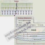
First, transfer to the cardboard the development of the parts shown in Figure 73. Draw those parts that will be glued to the left side of the model yourself. Recall how this is done. Copy onto the tracing paper those details near which the letter P (right) stands, then turn the tracing paper over and transfer the resulting image from it to cardboard.
Cut out all the details along the contour. Where the letter B stands, cut holes, and where the dot is, make punctures with an awl. Bend the workpieces along the fold lines, after drawing the tip of the awl along them with pressure. Then transfer to the drawing paper all the developments, except for parts 21, 50 ′ and 54 ′, the drawings of the developments of which are shown in Figures 74, 75. You need to cut and bend them in the same way as cardboard parts. Cut blanks of parts 21 from ordinary thin paper and, having smeared them with glue, screw them onto a rod with a diameter of 4 mm - you will get tubes 10 cm long.
Reamers 50' and 54' need to be cut out of the transparent film. It's better to label them like this. Put the film on the drawings of the scans, transfer the image of the parts to the film with an awl, and then cut them out.
Now prepare the parts shown in Figure 76 for assembly. Cut parts 74 and 65 from round sticks or pencils, parts 73 and 67 from spools of thread, part 46 and a cube measuring 1 X 1 X 1 cm from cork, part 72 - from tin or plexiglass, item 75 from thin rubber (for example, from an old bicycle inner tube), item 43 from a plastic or metal tube, and parts 17' and 51' from transparent film. Details 32, 48, 49, 53, 59 bend from the wire. If there is no thick wire at hand, then straighten ordinary paper clips.
So, the parts are prepared, you can start assembling. The assembly diagram of the cabin, launcher and frame is shown in Figure 72, wheels and axles - in Figure 76.
The cabin is a cardboard frame lined with paper. The frame is going like this. Glue the oil cooler 19 on the water radiator 18, and glue the frame 11 with the frame 12. Glue the radiators and frames on the base 14 in the places indicated by dashed lines.
Fasten frame 13 and radiator lining 20 on the same base, and glue part 2 on top.
Then glue parts 1, 4 and 3.
In the rear part of the cabin frame, install frame 9. Place part 6 on it and frame 12, and glue frame 7 to it.
Glue parts 8 and 10 on the back of the frame.
The final operation of the cab assembly is the skin sticker. First, prepare the parts for installation: glue the corners of the cover 61 of the hood and the roof 64, glue the parts 50 ′ and 54 ′ to the inside of parts 50 and 54, make notches in the hood 56 and bend the valves inward. Insert the rods 59 of the radiator grill into the holes of the base 14 of the cab and part 2.
Then, in order, stick parts 50, 63, 54, 5, 64, 61, 56, 58, 60,
62. Attach parts 15, 16, 17, 55, 52, 57 to the fender liner, footboard and headlight, respectively.
Place the launcher on the platform to be glued
from parts 26 and 27. Install a barrel on the platform: it is assembled from a sheathing 30 glued into a ring and bottoms 28. The hoops are imitated with two pieces of twine glued in the places indicated in the figure. Glue the prepared tubes 21 into a bag consisting of four rows - ten tubes in each. In the places indicated on the drawing, wrap this package several times with threads and fasten with bracket 23.
Glue the cradle 22 and fix the package on it. Then, from parts 24, 24' and 25, glue the base, after attaching a 1X1X1 cm cube of cork to part 24' (with glue). Pin the base with the washer under it to the platform with a nail (the nail should be inserted from the underside of the platform), glue the cradle with a package of tubes to the base. The assembled unit must rotate around the axis. If you want the bassinet to tilt, connect it to the base with a wire rod.
Rods 74 with tightly fitted drums 73 and loose washers 72 form axes. Rings 76 are glued onto the drums of the middle and rear axles, between which a belt 75 is put on.
A large pulley is mounted on the middle axle, consisting of a drum 67 with a paper strip 38 screwed onto it and two discs 68. It can only be installed after the frame has been assembled.
The frame of the model is assembled from two spars and five transverse bars. Bend the spars 34 with the letter P and glue paper strips 38 to them from below (their length is determined locally). Insert bushings 43 into the holes of the spars and put the finished parts on the axles. Make a beam 33, four beams 35 and glue them between the spars 34. Reinforce the front part of the frame with a bumper 31 with two hooks 32, and the rear part with a part 36 with one hook. Glue parts 44 to the frame from above.
Assemble the wheels according to the scheme shown in Figure 76. It does not require special explanations. We only note that part 71 needs to be bent along the center line and give it a conical shape. It's done
so. Insert the needle of the measuring compass into the center of the cross on the scan, and push the fold line with the second needle. Now the workpiece is easy to give a conical shape. Fit the finished wheels firmly on the glue on the axle so that the ends of the latter protrude 2 mm beyond the wheel disks.
Glue the finished cabin and platform with the launcher to the frame. On the left side, attach a gas tank to the platform, glued from casing 40 and frames 39. Roll up part 41 - it imitates the neck of the tank - and glue it into the tank hole from above. Glue a cover on the neck, consisting of two parts 42. On the right side, glue a spare parts box to the platform (item 47) and make a step, glue aprons 45 on the back, and on top - the base for the DP-10 electric motor (item 46). For a micromotor of another type, the base will have to be designed by yourself.
Fasten the microelectric motor to the base with adhesive tape or a cardboard clamp, put a small pulley on the shaft, connect it with a belt with a large pulley mounted on the middle axis (see Fig. 76 "Kinematic diagram"). Connect the engine to the control panel (RC), consisting of a battery and a three-position switch. Do a road test. The model must execute three commands: "Forward", "Back" and "Stop". If there are flaws, eliminate them and proceed to the final stage - finishing the model.
Finishing the model consists in the sticker of small details. Install handles 48 and 49, holders 53 of mirrors 51 in their places. Glue parts 51' and 17' of the film on the mirrors and headlights, having previously placed pieces of foil under them.
The model is assembled. Chassis paint the finished model with black ink, and the cockpit and launcher with green gouache or tempera. You can draw a Guards badge on the cabin doors. To make the model stronger and the paint not smear, cover it with colorless varnish or PVA glue.


"Katyusha"- the popular name for rocket artillery combat vehicles BM-8 (with 82 mm shells), BM-13 (132 mm) and BM-31 (310 mm) during the Great Patriotic War. There are several versions of the origin of this name, the most likely of them is associated with the factory mark "K" of the manufacturer of the first BM-13 combat vehicles (Voronezh Plant named after the Comintern), as well as with the popular song of the same name at that time (music by Matvey Blanter, lyrics by Mikhail Isakovsky).
(Military Encyclopedia. Chairman of the Main Editorial Commission S.B. Ivanov. Military Publishing. Moscow. In 8 volumes -2004. ISBN 5 - 203 01875 - 8)
The BM-13 received its baptism of fire on July 14, 1941, when the battery fired the first salvo from all installations at the Orsha railway station, where a large amount of enemy manpower and military equipment was concentrated. As a result of a powerful fire strike simultaneously by 112 rockets, a fire glow rose over the station: enemy echelons were burning, ammunition was exploding. An hour and a half later, Flerov's battery fired a second salvo, this time at the crossing of the Orshitsa River, on the approaches to which a lot of German equipment and manpower had accumulated. As a result, the enemy's crossing was disrupted, and he failed to develop success in this direction.
The first experience of using a new missile weapon showed its high combat effectiveness, which was one of the reasons for its fastest commissioning and equipping the Ground Forces with it.
The restructuring of the industry associated with the production of rocket weapons was carried out in short time, a large number of enterprises were attracted to its production (already in July-August 1941 - 214 factories), which ensured the entry of this military equipment into the troops. In August-September 1941, mass production of BM-8 combat mounts with 82-mm rockets was launched.
Simultaneously with the deployment of production, work continued on the creation of new and improvement of existing samples of rockets and launchers.
On July 30, 1941, a special design bureau (SKB) at the Moscow Kompressor plant began to work - the head design bureau for launchers, and the plant itself became the lead enterprise for their production. This SKB, under the leadership of the head and chief designer Vladimir Barmin, developed 78 samples of launchers during the war years various types mounted on cars, tractors, tanks, railway platforms, river and sea ships. Thirty-six of them were put into service, mastered by industry and used in combat.
Much attention was paid to the production of rockets, the creation of new and the improvement of existing samples. The 82-mm M-8 rocket projectile underwent modernization, powerful high-explosive rocket projectiles were created: 132-mm M-20, 300-mm M-30 and M-31; extended range - M-13 DD and improved accuracy - M-13 UK and M-31 UK.
With the beginning of the war, as part of the Armed Forces of the USSR, special troops for the combat use of rocket weapons. These were rocket troops, but during the war they were called guards mortar units (GMCH), and later - rocket artillery. The first organizational form of the HMC was separate batteries and divisions.
By the end of the war, rocket artillery had 40 separate divisions (38 M-13 and 2 M-8), 115 regiments (96 M-13 and 19 M-8), 40 separate brigades(27 M-31 and 13 M-31-12) and 7 divisions - a total of 519 divisions in which there were over 3000 combat vehicles.
The legendary Katyushas took part in all major operations during the war.
The fate of the first separate experimental battery was cut short in early October 1941. After baptism of fire near Orsha, the battery successfully operated in the battles near Rudnya, Smolensk, Yelnya, Roslavl and Spas-Demensk. During the three months of hostilities, Flerov's battery not only inflicted considerable material damage on the Germans, it also contributed to raising the morale of our soldiers and officers, exhausted by continuous retreats.
The Nazis staged a real hunt for new weapons. But the battery did not stay long in one place - having fired a volley, it immediately changed its position. A tactical technique - a volley - a change of position - was widely used by Katyusha units during the war.
In early October 1941, as part of the grouping of troops on the Western Front, the battery ended up in the rear of the Nazi troops. When moving to the front line from the rear on the night of October 7, she was ambushed by the enemy near the village of Bogatyr, Smolensk region. Most of battery personnel and Ivan Flerov died, having shot all the ammunition and blowing up combat vehicles. Only 46 soldiers managed to get out of the encirclement. The legendary battalion commander and the rest of the fighters, who fulfilled their duty with honor to the end, were considered "missing." And only when it was possible to find documents from one of the army headquarters of the Wehrmacht, which reported what actually happened on the night of October 6-7, 1941 near the Smolensk village of Bogatyr, Captain Flerov was excluded from the list of missing persons.
For heroism, Ivan Flerov was posthumously awarded the Order of the Patriotic War of the 1st degree in 1963, and in 1995 he was awarded the title of Hero Russian Federation posthumously.
In honor of the feat of the battery, a monument was erected in the city of Orsha and an obelisk near the city of Rudnya.