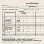
Symbols on the political map. Geographic map
Definition 1
Cartographic conventional signs - symbolic graphic designations that are used to depict various objects and their characteristics on cartographic images (maps and topographic maps).
Sometimes symbols are called map legend.
Types of conventional signs by scale
Depending on the scale, $3$ groups of conventional signs are distinguished:
- scale (areal and linear);
- off-scale (point);
- explanatory.
With the help of areal scale signs, extended objects are displayed on a map scale. Scale signs on the map allow you to determine not only the location of the object, but also its size and shape.
Example 1
Scale marks are the territory of the state on a $1:10,000,000 scale map or a reservoir on a $1:10,000 scale map.
Linear conventional signs are used to display objects that are significantly extended in one dimension, for example, roads. Consistent with the scale on such signs, only one dimension (in which the object is the most extended), while the other is off-scale. The position of an object is determined by a conditional or explicit center line.
Out-of-scale point symbols are used on maps to represent objects whose dimensions are not expressed on the map. The largest cities on the world map are displayed as off-scale signs - dots. The actual placement of the object is determined by the main point of the point symbol.
The main point is placed at off-scale signs as follows:
- in the center of the figure near symmetrical signs;
- in the middle of the base for signs with a wide base;
- at the top right angle, which is the base, if the sign has such an angle;
- in the center of the lower figure, if the sign is a combination of several figures.
Explanatory signs are intended to characterize local objects and their varieties. Explanatory signs may indicate the number of railroad tracks, the direction of the river.
Remark 1
On large-scale maps, the signs of individual objects are indicated separately, on smaller-scale maps, objects of the same type are grouped and applied with one sign.
Conventional signs by content
- signs and signatures of settlements;
- signs of individual local objects;
- signs of individual relief elements;
- transport infrastructure signs;
- signs of hydrographic network objects;
- signs of soil and vegetation cover;
Signs and signatures of settlements
On maps at a scale of $1:100,000 and larger, all settlements are indicated along with the signature of their names. Moreover, the names of cities are applied in direct capital letters, rural settlements - in lowercase letters, urban and suburban settlements - in lowercase oblique letters.
Large-scale maps display the exterior outline and layout, highlighting major highways, businesses, prominent knowledge and landmarks.
Example 2
On the $1:25 \ 000$ and $1:50 \ 000$ scale maps, the type (fireproof or non-fireproof) of the development is displayed in color.
In the figure below - signs of settlements used on maps different eras.
Signs of individual local objects
Separate local objects, which are landmarks, are drawn on the map mainly with off-scale signs. It can be towers, mines, adits, churches, radio masts, remnant rocks.
Signs of individual relief elements
Relief elements are marked on the map with appropriate signs.
Remark 2
An object of natural origin is represented by lines and signs in brown.
Transport infrastructure signs
To transport infrastructure objects displayed on topographic maps, include the road and railway network, structures and bridges.
When plotted on a map, paved roads (motorways, improved highways, improved dirt roads) and unpaved roads are distinguished. All paved roads are plotted on the map, indicating the width and material of the pavement.
The color of the road on the map indicates its type. Highways and highways are applied in orange, improved dirt roads in yellow (occasionally orange), unpaved country roads, field, forest and seasonal roads without color.
Signs of objects of the hydrographic network
The following elements of the hydrographic network are depicted on the map - the coastal part of the seas, rivers, lakes, canals, streams, wells, ponds and other bodies of water.
Reservoirs are plotted on the map if their area on the image is more than $1 mm^2$. In another case, a body of water is applied only because of high importance, for example in dry areas. Objects are labeled with their name.
The characteristics of the objects of the hydrographic network are indicated next to the signature of the name of the object. In particular, they indicate in the form of a fraction the width (numerator), depth and nature of the soil (denominator), as well as the speed (in m / s) and direction of the current. Also listed along with specifications hydraulic structures- ferries, dams, locks. Rivers and canals are mapped in full. In this case, the type of display is determined by the width of the object and the scale of the map.
Remark 4
In particular, at a map scale of more than $1:50,000$, objects less than $5$ m wide, at a map scale of less than $1:100,000$ - less than $10$ m, are depicted by a $1$ line, and wider objects by two lines. Also, $2$ lines designate channels and ditches with a width of $3$ m or more, and with a smaller width - one line.
On large-scale maps, blue circles indicate wells, the letter “k” or “art.k” is placed next to it in the case of an artesian well. In dry areas, wells and water supply facilities are shown with enlarged signs. Water pipelines on maps are shown by lines with dots of blue color: solid lines - ground, broken - underground.
Land cover signs
Often, when displaying land cover on a map, a combination of scale and off-scale symbols is used. Signs denoting forests, shrubs, gardens, swamps, meadows, nature are large-scale, and individual objects, for example, separately standing trees- off-scale.
Example 3
The swampy meadow is displayed on the map as a combination of conventional symbols of a meadow, bushes and a swamp in a closed contour.
The contours of areas of terrain occupied by a forest, shrub or swamp are applied with a dotted line, except when the boundary is a fence, roads or other linear local object.
Forested areas are indicated in green with a symbol indicating the type of forest (coniferous, deciduous or mixed). Areas with forest growth or nurseries are plotted in pale green on the map.
Example 4
The figure below shows a coniferous tree on the left. Pine forest with an average tree height of $25$ meters and a width of $0.3$ m, as well as a typical distance between tree trunks of $6$ m. The figure on the right shows a deciduous maple forest with a tree height of $12$ m and a trunk width of with an average of $3$ meters.
Swamps are shown on the map with blue horizontal shading. At the same time, the type of hatching shows the degree of passability: intermittent hatching - passable, solid - difficult and impassable.
Remark 5
Swamps with a depth of less than $0.6$ m are considered passable.
Vertical shading in blue on the map indicates salt marshes. As well as for swamps, solid shading indicates impenetrable solonchaks, broken shading indicates passable ones.
Colors of symbols on topographic maps
The colors that depict objects on maps are universal for all scales. Black dashed marks - buildings, structures, local objects, strong points and boundaries, brown dashed marks - relief elements, blue - hydrographic network. Areal signs of light blue color - a mirror of waters of hydrographic network objects, green color - areas of tree and shrub vegetation, orange color - quarters with fire-resistant buildings and highways, yellow - quarters with non-fire-resistant buildings and improved dirt roads.
Remark 6
On military and special cards, special conventions.
Scale, or contour, conditional topographic signs are used to depict local objects that, by their size, can be expressed on a map scale, that is, their dimensions (length, width, area) can be measured on a map. For example: a lake, a meadow, large gardens, quarters of settlements. The contours (outer boundaries) of such local objects are depicted on the map with solid lines or dotted lines, forming figures similar to these local objects, but only in a reduced form, that is, on a map scale. Solid lines show the contours of quarters, lakes, wide rivers, and the contours of forests, meadows, swamps - dotted lines.
Figure 31.
Structures and buildings, expressed on the scale of the map, are depicted by figures similar to their actual outlines on the ground and are painted over in black. Figure 31 shows several scale (a) and off-scale (b) symbols.
Off-scale symbols
Explanatory topographic signs serve to additionally characterize local objects and are used in combination with large-scale and off-scale signs. For example, a figurine of a conifer or deciduous tree inside the contour of the forest shows the dominant tree species in it, the arrow on the river indicates the direction of its flow, etc.
In addition to signs, full and abbreviated signatures are used on the maps, as well as digital characteristics of some objects. For example, the signature "mash." with the sign of the plant means that this plant is a machine-building plant. The names of settlements, rivers, mountains, etc. are fully signed.
Numerical designations are used to indicate the number of houses in rural settlements, the height of the area above sea level, the width of the road, the characteristics of the carrying capacity and the size of the bridge, as well as the size of the trees in the forest, etc. Numerical designations related to conventional relief signs are printed in brown , width and depth of rivers in blue, everything else in black.
Let us briefly consider the main types of topographic symbols for depicting the area on the map.
Let's start with terrain. Due to the fact that observation conditions, terrain passability and its protective properties largely depend on its nature, the terrain and its elements are depicted on all topographic maps in great detail. Otherwise, we could not use the map to study and evaluate the area.
In order to clearly and fully imagine the area on the map, you must first of all be able to quickly and correctly determine on the map:
Types of irregularities earth's surface and their relative position;
Mutual excess and absolute heights of any points of the terrain;
The shape, steepness and length of the slopes.
On modern topographic maps, the relief is depicted by contour lines, that is, curved closed lines, the points of which are located on the ground at the same height above sea level. In order to better understand the essence of the depiction of the relief by contour lines, let us imagine an island in the form of a mountain, gradually flooded with water. Let us assume that the water level successively stops at regular intervals equal in height to h meters (Fig. 32).
Then each water level will have its own coastline in the form of a closed curved line, all points of which have the same height. These lines can also be considered as traces of a section of terrain irregularities by planes parallel to the level surface of the sea, from which heights are counted. Based on this, the distance h in height between the secant surfaces is called the height of the section.

Figure 32.
So if all lines equal heights project on the level surface of the sea and depict them on a scale, then we will get an image of the mountain on the map in the form of a system of curved closed lines. These will be horizontal.
In order to find out whether it is a mountain or a basin, there are slope indicators - small dashes that are applied perpendicular to the horizontal lines in the direction of lowering the slope.

Figure 33.
The main (typical) landforms are shown in Figure 32.
The height of the section depends on the scale of the map and on the nature of the relief. normal height section is considered to be a height equal to 0.02 of the map scale value, that is, 5 m for a map of a scale of 1:25 OOO and, respectively, 10, 20 m for maps of scales 1: 50,000, 1: 100,000. Contours on the map corresponding to the height set for it sections are drawn by solid lines and are called main or solid contour lines. But it happens that at a given height of the section, important details of the relief are not expressed on the map, since they are located between the cutting planes.
Then half semi-horizontals are used, which are drawn through half the main height of the section and are plotted on the map with broken lines. To determine the count of contour lines when determining the height of points on the map, all solid contour lines corresponding to five times the height of the section are drawn thickened (thickened contour lines). So, for a map with a scale of 1: 25,000, each horizontal line corresponding to the height of the section 25, 50, 75, 100, etc. will be drawn as a thickened line on the map. The main height of the section is always indicated under the south side of the map frame.
The heights of the hills on the ground depicted on our maps are counted from the level Baltic Sea. The heights of points on the earth's surface above sea level are called absolute, and the excess of one point above another is called relative excess. Horizontal marks - digital inscriptions on them - indicate the height of these terrain points above sea level. The top of these numbers is always facing upward slope.

Figure 34.
Marks of command heights, from which the terrain from the most important objects on the map (large settlements, road junctions, passes, mountain passes, etc.) is better viewed than others, are applied in large numbers.
With the help of contour lines, you can determine the steepness of the slopes. If you look closely at Figure 33, you can see from it that the distance between two adjacent contours on the map, called the laying (with a constant section height), changes depending on the steepness of the slope. The steeper the slope, the smaller the laying and, conversely, the more flat the slope, the greater the laying. Hence the conclusion follows: steep slopes on the map will differ in the density (frequency) of contour lines, and in flat places the contour lines will be less frequent.
Usually, to determine the steepness of the slopes, a drawing is placed on the margins of the map - laying scale(Fig. 35). Along the lower base of this scale are numbers that indicate the steepness of the slopes in degrees. On the perpendiculars to the base, the corresponding values of the deposits are plotted on the scale of the map. On the left side, the scale of embeddings is built for the main height of the section, on the right - at five times the height of the section. To determine the steepness of the slope, for example, between points a-b(Fig. 35), you need to take this distance with a compass and set aside on the scale and read the steepness of the slope - 3.5 °. If it is required to determine the steepness of the slope between the horizontals thickened n-t, then this distance should be set aside on the right scale and the steepness of the slope in this case will be equal to 10 °.

Figure 35.
Knowing the property of contour lines, it is possible to determine from the map and the shape various kinds stingrays (Fig. 34). In an even slope, the inceptions will be approximately the same throughout its entire length, in a concave one they increase from the top to the sole, and in a convex one, on the contrary, the inceptions decrease towards the sole. In wavy slopes, the laying changes according to the alternation of the first three forms.
When depicting relief on maps, not all of its elements can be expressed as contour lines. So, for example, slopes with a steepness of more than 40 ° cannot be expressed as horizontals, since the distance between them will be so small that they will all merge. Therefore, slopes with a steepness of more than 40 ° and steep are indicated by horizontal lines with dashes (Fig. 36). Moreover, natural cliffs, ravines, gullies are indicated in brown, and artificial embankments, excavations, mounds and pits are indicated in black.

Figure 36.
Consider the main conditional topographic signs for local objects. Settlements are depicted on the map with the preservation of external borders and planning (Fig. 37). All streets, squares, gardens, rivers and canals, industrial enterprises, outstanding buildings and structures that have the value of landmarks are shown. For better visibility, fire-resistant buildings (stone, concrete, brick) are painted over in orange, and blocks with non-fire-resistant buildings are painted in yellow. The names of settlements on the maps are signed strictly from west to east. The type of administrative value of a settlement is determined by the type and size of the font (Fig. 37). Under the signature of the name of the villages, you can find a number indicating the number of houses in it, and if there are locality district or village council, the letters “RS” and “SS” are additionally put.

Figure 37-1.

Figure 37-2.
No matter how poor the area is in local objects or, on the contrary, saturated, there are always separate objects on it, which stand out from the rest in size and are easily recognized on the ground. Many of them can be used as landmarks. This should include: factory chimneys and outstanding buildings, tower-type buildings, wind turbines, monuments, auto columns, signs, kilometer posts, stand-alone trees, etc. (Fig. 37). Most of them, but due to their size, cannot be shown on the scale of the map, so they are depicted on it with off-scale signs.
The road network and crossings (Fig. 38, 1) are also depicted by off-scale conventional signs. Data on the width of the carriageway, road surface, indicated on conventional signs, make it possible to evaluate them throughput, carrying capacity, etc. Railways, depending on the number of tracks, are indicated by dashes across the conventional sign of the road: three dashes - a three-track railway, two dashes - a double-track railway. On the railways stations, embankments, cuts, bridges and other structures are shown. At bridges longer than 10 m, its characteristic is signed.

Figure 38-1.

Figure 38-2.

Figure 39.
For example, the signature at the bridge ~ means that the length of the bridge is 25 m, the width is 6 m, and the load capacity is 5 tons.
Hydrography and structures associated with it (Fig. 38, 2), depending on the scale, are shown with greater or lesser detail. The width and depth of the river is signed as a fraction 120/4.8, which means:
The width of the river is 120 m and its depth is 4.8 m. The speed of the river flow is shown in the middle of the symbol with an arrow and a number (the number indicates the speed of 0.1 meters per second, and the arrow indicates the direction of the flow). On rivers and lakes, the height of the water level in the low water period (mark of the water's edge) in relation to sea level is also signed. At the fords, it is signed: in the numerator - the depth of the ford in meters, and in the denominator - the quality of the soil (T - hard, P - sandy, B - viscous, K - rocky). For example, br. 1.2/k means that the ford is 1.2 m deep and the bottom is rocky.
The soil and vegetation cover (Fig. 39) is usually depicted on maps with large-scale symbols. These include forests, shrubs, gardens, parks, meadows, marshes, salt marshes, as well as sands, rocky surfaces, and pebbles. In the forests, its characteristics are indicated. For example, at mixed forest(spruce with birch) are the numbers 20/\0.25 - this means that the average height of trees in the forest is 20 m, their average thickness is 0.25 m, the average distance between tree trunks is 5 meters.

Figure 40.
Swamps are depicted depending on their passability on the map: passable, difficult to pass, impassable (Fig. 40). Passable swamps have a depth (to solid ground) of no more than 0.3-0.4 m, which is not shown on the maps. The depth of difficult and impenetrable swamps is signed next to the vertical arrow indicating the location of the sounding. On the maps, the cover of swamps (grass, moss, reed), as well as the presence of forests and shrubs on them, are shown with the corresponding conventional signs.
Hilly sands differ from flat sands and are indicated on the map by a special symbol. In the southern steppe and semi-steppe regions, there are areas of terrain with soil abundantly saturated with salt, which are called solonchaks. They are wet and dry, some are impassable, while others are passable. On the maps, they are indicated by conventional signs - “shading” in blue. The image of solonchaks, sands, swamps, soil and vegetation cover is shown in Figure 40.
Off-Scale Conventional Signs of Local Items
Answer: Off-scale symbols are used to depict small local objects that are not expressed on the scale of the map - detached trees, houses, wells, monuments, etc. If they were depicted on the scale of the map, they would turn out to be in the form of a point. Examples of the image of local objects by off-scale conventional signs are shown in Figure 31. The exact location of these objects depicted by off-scale conventional signs (b) is determined by the center symmetrical figure(7, 8, 9, 14, 15), in the middle of the base of the figure (10, 11), at the top of the corner of the figure (12, 13). Such a point on the figure of an off-scale symbol is called the main point. In this figure, the arrow shows the main points of the conventional signs on the map.
This information is useful to remember in order to correctly measure the distance between local objects on the map.
(This issue is discussed in detail in question No. 23)
Explanatory and conventional signs of local objects
Answer: Types of topographic symbols
The area on maps and plans is depicted by topographic symbols. All conventional signs of local objects according to their properties and purpose can be divided into the following three groups: contour, scale, explanatory.
Conventional signs There are contour, linear and off-scale.
- contour(areal) signs shown, for example, lakes;
- Linear signs - rivers, roads, canals.
- Off-scale signs on the plans, for example, wells, springs are noted, and on geographical maps - settlements, volcanoes, waterfalls.
Rice. 1. Examples of off-scale, linear and area symbols

Rice. Basic symbols
Rice. Conventional signs of the area
Contours
There is a separate category of symbols - isolines, i.e., lines connecting points with the same values of the depicted phenomena (Fig. 2). Lines of equal atmospheric pressure called isobars, lines of equal air temperature - isotherms, lines of equal heights of the earth's surface - isohypses or horizontal lines.

Rice. 2. Examples of isolines
Mapping methods
To depict geographical phenomena on maps, various methods are used. ways .Way of habitats show areas of distribution of natural or social phenomena, such as animals, plants, some minerals. traffic signs used to show sea currents, winds, traffic flows. high quality background show, for example, states on political map, a quantitative background - division of the territory according to some quantitative indicator(Fig. 3).

Rice. 3. Cartographic methods: a - method of areas; b - signs of movement; c - method of qualitative background; d - quantitative background - dotted signs
To show the average value of the phenomenon in any territory, it is most expedient to use the principle of equal intervals. One way to get an interval is to divide the difference between the largest and smallest exponent by five. For example, if the largest indicator is 100, the smallest is 25, the difference between them is 75, its 1/5 -15, then the intervals will be: 25-40, 40-55, 55-70, 70-85 and 85-100 . When showing these intervals on the map, a lighter background or sparse shading depicts a lower intensity of the phenomenon, darker tones and dense shading - a greater one. This type of mapping is called cartogram(Fig. 4).

Rice. 4. Examples of cartograms and cartograms
To the way chart diagrams are used to show the total magnitude of a phenomenon in an area, for example, electricity production, school enrollment, stocks fresh water, the degree of plowed land, etc. map called a simplified map that does not have a degree network.
Relief depiction on plans and maps
On maps and plans, relief is shown using contour lines and elevations.
Horizontals, as you already know, these are lines on a plan or map connecting points on the earth's surface that have the same height above ocean level (absolute height) or above the level taken as a reference point (relative height).

Rice. 5. Image of relief by contour lines
In order to depict a hill on a plan, you need to define it relative height, which shows how far vertically one point on the earth's surface is higher than another (Fig. 7).

Rice. 6. Image of a hill on a plane

Rice. 7. Determination of relative height
Relative height can be determined using a level. Level(from fr. niveau- level, level) - a device for determining the difference in height between several points. The device, usually mounted on a tripod (tripod), is equipped with a telescope adapted for rotation in a horizontal plane and a sensitive level.
Spend hill leveling - this means measuring its western, southern, eastern and northern slopes from the bottom to the top with the help of a level and driving in pegs in those places where the level was installed (Fig. 8). Thus, four pegs will be driven in at the bottom of the hill, four - at a height of 1 m from the ground, if the height of the level is 1 m, etc. The last peg is driven in at the top of the hill. After that, the position of all the pegs is applied to the terrain plan and first all points with a relative height of 1 m are connected with a smooth line, then - 2 m, etc.

Rice. 8. Hill flattening
Please note: if the slope is steep, the horizontals on the plan will be located close to each other, if it is gentle, they will be far apart.
Small dashes drawn perpendicular to the horizontal lines are berghashes. They show in which direction the slope goes down.
Horizontals on the plans depict not only hills, but also depressions. In this case, the berghashes are turned inward (Fig. 9).

Rice. 9. Image by contour lines various forms relief
Steep slopes of cliffs or ravines on the maps are indicated by small teeth.
The height of a point above mean ocean level is called absolute height. In Russia, all absolute heights are calculated from the level of the Baltic Sea. Thus, the territory of St. Petersburg is on average 3 m above the water level in the Baltic Sea, the territory of Moscow is 120 m, and the city of Astrakhan is 26 m below this level. Elevation marks on geographical maps indicate the absolute height of points.
On the physical map the relief is depicted with the help of layered coloring, i.e., with a color of different intensity. For example, areas with a height of 0 to 200 m are painted over in green. At the bottom of the map there is a table that shows which color corresponds to which height. This table is called height scale.
Conventional signs of topographic maps
Tikhonova L.Ya. geography teacher, MBOU "Lyceum No. 3", Prokhladny, KBR


Do you know the symbols?

Read the letter
Hello mother!
We went hiking. We left early in the morning
out, went on up,
turned west and approached
.To the right of us was,
. Then, past along
by we returned to.

The glorious hero Alyosha Popovich lived in Russia,
and he only knew how to lie on the stove, and with Tugarin
Let's fight the snake. He went once gold
free the people from the paws of the Tugarins.
His path lay through birch forest , past the rotten
swamps through which path was. I went
Alyosha into the very thicket of the forest and sees the picturesque lake ,
and next to him forester's house . He asks the forester
how to get him river , where is the Tugarin army
located. And the old man answers him, the way is long
you have to. First you go to dirt road ,
turn into Pine forest . There you will see golodets ,
boldly go from him to spring , at the spring
have a deep ravine , you will cross it and you will see meadow ,
standing on that meadow lonely tree .
If you approach him, Tugarin himself will appear.
Write the story in symbols
http://aida.ucoz.ru

Determine the direction

Measure the distance using the scale in fig. 39
in 1 cm 100 m
- Determine the scale of the plan.
- Measure the distance from the birch to the barn with a ruler.
- Calculate the distance using the scale.
- Determine the distance from the birch to the point 162.3 m; to the lake; to the wooden bridge.
0.9 cm
0.9 cm x 100 m = 90 m

Draw a plan of the area
An observer stands in the center of the area in the meadow. He sees:
- North, 300 m, school
- East, 250 m, bushes
- N-W, 400 m, orchard
- To the south, 150 m, the lake, the eastern shore is swampy
- South-west, 200 m, bush
- On the s-v, 450 m, mixed forest
- 3, 200 m, light forest
- South-east, 100 m, well
M: in 1cm 100m
Plan from one point is called polar
http://aida.ucoz.ru

Draw a route plan for the area (M 1: 10000m)
The guys went from school (v. 1) on an excursion (the school is located in the northwest area)
v.1 → v.2 - on c. 800 m along the path through the orchard,
v.2 - a well on the bank of the river. Belka, the river flows from the south. us.
v.2→v.3 - 500 m against the river along the path through the bushes,
v.3 - spring,
t.3 → t.4 - on the s-w. on a dirt road through the field 400 m.
v.4 - windmill, south of point 4 we saw a lake, the eastern shore of which is swampy,
t.4→t.5 - to the south-west. 400 m along the path through the meadow to the birch (v. 5),
vol.5 → vol.1 – back to school on a dirt road through woodlands
http://aida.ucoz.ru

draw a sign

draw a sign
windmill

draw a sign

draw a sign
rare forest

draw a sign
free standing tree
Topographic (cartographic) symbols - symbolic dashed and background symbols of terrain objects used to depict them on topographic maps .
For topographic conventional signs, a common designation (in style and color) of homogeneous groups of objects is provided, while the main signs for topographic maps different countries do not differ significantly from each other. As a rule, topographic symbols convey the shape and size, location, and some qualitative and quantitative characteristics of objects, contours, and relief elements reproduced on maps.
Topographic symbols are usually divided into large-scale(or areal), off-scale, linear and explanatory.
scale, or areal conventional signs serve to depict such topographic objects that occupy a significant area and whose dimensions in terms of plan can be expressed in scale given map or plan. An areal symbol consists of a boundary symbol of an object and symbols that fill it or a symbolic coloring. The outline of an object is shown as a dotted line (outline of a forest, meadow, swamp), a solid line (outline of a reservoir, settlement) or a symbol of the corresponding boundary (ditch, fence). Filling characters are located inside the contour in a certain order (arbitrarily, in a checkerboard pattern, in horizontal and vertical rows). Areal symbols allow not only to find the location of an object, but also to evaluate its linear dimensions, area and outlines.
Out-of-scale conventional symbols are used to convey objects that are not expressed on the scale of the map. These signs do not allow us to judge the size of the depicted local objects. The position of the object on the ground corresponds to a certain point of the sign. For example, for the sign correct form(for example, a triangle denoting a point of a geodetic network, a circle - a cistern, a well) - the center of the figure; for a sign in the form of a perspective drawing of an object (factory chimney, monument) - the middle of the base of the figure; for a sign with a right angle at the base (wind turbine, gas station) - the top of this angle; for a sign that combines several figures (radio tower, oil rig), the center of the lower one. It should be noted that the same local objects on large-scale maps or plans can be expressed by areal (scale) conventional signs, and on small-scale maps - off-scale conventional symbols. signs.
Linear conventional signs are designed to depict extended objects on the ground, such as iron and car roads, clearings, power lines, streams, borders and others. They occupy an intermediate position between large-scale and off-scale conventional signs. The length of such features is expressed at the scale of the map, while the width on the map is not to scale. Usually it turns out to be greater than the width of the depicted terrain object, and its position corresponds to the longitudinal axis of the symbol. Linear topographic symbols also depict horizontal lines.
Explanatory symbols are used to additionally characterize the local objects shown on the map. For example, the length, width and carrying capacity of the bridge, the width and nature of the road surface, the average thickness and height of trees in the forest, the depth and nature of the ford soil, etc. Various inscriptions and proper names of objects on the maps are also explanatory; each of them is performed in a set font and letters of a certain size.
On topographic maps, as their scale decreases, homogeneous conventional signs are combined into groups, the latter into one generalized sign, etc., in general, the system of these designations can be represented as a truncated pyramid, which is based on signs for topographic scale plans 1: 500, and at the top - for survey topographic maps at a scale of 1: 1,000,000.
The colors of topographic symbols are the same for maps of all scales. Line marks of lands and their contours, buildings, structures, local objects, strongholds and boundaries are printed in black when published; relief elements - brown; reservoirs, streams, swamps and glaciers - blue (water mirror - light blue); areas of tree and shrub vegetation - green (dwarf forests, elfins, shrubs, vineyards - light green); neighborhoods with fire-resistant buildings and highways - orange; neighborhoods with non-fireproof buildings and improved dirt roads in yellow.
Along with conventional signs for topographic maps, conditional abbreviations of their own names of political and administrative units (for example, Moscow region - Mosk.) and explanatory terms (for example, power plant - el.-st., swamp - bol., southwestern - SW) . Standardized fonts for inscriptions on topographic maps allow, in addition to conventional signs, to give essential information. For example, fonts for the names of settlements display their type, political and administrative significance and population, for rivers - the size and the possibility of navigation; fonts for height marks, characteristics of passes and wells make it possible to highlight the main ones, etc.
The relief of the terrain on topographic plans and maps is depicted by the following methods: strokes, hillshading, colored plastics, marks and contour lines. On large-scale maps and plans, the relief is depicted, as a rule, by the contour lines method, which has significant advantages over all other methods.
All conventional signs of maps and plans should be clear, expressive and easy to draw. Conventional signs for all scales of maps and plans are established by regulatory and instructive documents and are mandatory for all organizations and departments performing survey work.
Taking into account the variety of agricultural lands and objects, which does not fit into the framework of mandatory symbols, land management organizations issue additional symbols reflecting the specifics of agricultural production.
Depending on the scale of the maps or plan, local items are shown in varying detail. So, for example, if on a plan of scale 1: 2000 in a settlement not only individual houses, but also their shape are shown, then on a map of scale 1: 50,000 - only quarters, and on a map of scale 1: 1,000,000 the whole city will be indicated small circle. Such a generalization of the elements of the situation and relief in the transition from larger scales to smaller scales is called map generalization .